


BE1-87G - Introduction iii
CONTENTS
SECTION 1 GENERAL INFORMATION 1-1
Description ..............................................1-1
Applications .............................................1-1
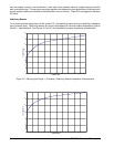
Variable Restraint Characteristic ..........................1-3
Design Highlights ......................................1-3
Model and Style Number ...................................1-3
Style Number Example .................................1-3
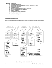
Style Number Identification Chart .........................1-4
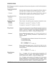
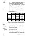
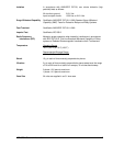
Specifications ............................................1-5
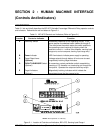
SECTION 2 CONTROLS AND INDICATORS 2-1
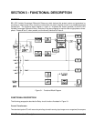
SECTION 3 FUNCTIONAL DESCRIPTION 3-1
General .................................................3-1
Functional Description .....................................3-1
Current Transformers ...................................3-1
Stabilizing Reactor .....................................3-2
Bandpass Filters ......................................3-3
Comparator ..........................................3-3
Outputs .............................................3-3
Targets (Optional) .....................................3-3
Push-To-Energize (Optional) .............................3-3
Power Supply Status Output (Optional) .....................3-3
Power Supply .........................................3-4
SECTION 4 INSTALLATION 4-1
General .................................................4-1
Dielectric Test ............................................4-1
Mounting ................................................4-1
Relay ...............................................4-1
S1 Case, Outline Dimensions ............................4-1
S1 Case, Double-Ended, Outline Dimensions ................4-2
S1 Case, Panel Drilling Diagram ..........................4-3
Stabilizing Reactor .....................................4-4
S1 Case And Reactor, Outline Dimensions ..................4-5
Connections .............................................4-5
Typical DC Control Connections ..........................4-6
Single-Phase Sensing Input Connections ...................4-6
Three-Phase Sensing Input Connection ....................4-7
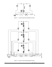
Single Phase Internal Connection Diagram ..................4-8
Three Phase Internal Connection Diagram ..................4-9
SECTION 5 TESTING AND SETTING 5-1
General .................................................5-1
Relay Operating Precautions ................................5-1
Dielectric Test ............................................5-1
Equipment Required .......................................5-1
Operational Test Procedure .................................5-2
Operational Test Setup .................................5-2
Location Of Assemblies (Single-Phase Only) ................5-3
TP-1 And TP-2 On Single-Phase Relays ....................5-3
Single-Phase Trip And Dropout Test .......................5-4