


BE1-87G - Testing And Setting 5-11
I
d
1000
4.16×
3
0.15×200
138.8
30
4.6 × CT rating
Inequality
(1)
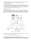
is met with CT #2, but not with CT #1. However, since the locked rotor current is only 4.8 times
CT rating [vs. the assumption of 20 times rated for inequality
(1)
], the application is suitable.
SFR = (100/50)*(0.36/0.19) = 3.8
Using the SFR 4 column of Table 5-1, a 0.8 ampere setting is indicated. However, based on the note
accompanying this table, choose the next higher setting of 1.6, because CT #1 has a T classification, and CT
#2 has a C classification. The T classification indicates that the CT has significant secondary leakage
inductance which somewhat degrades the transient performance. This is a concern during motor starting
because a slowly decaying offset component develops in at least one phase.
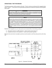
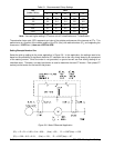
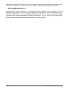
Setting Example Number Two
Select the pick-up setting for the generator application in Figure 5-9. In this application, the settings need to be
based on the probability of significant dissimilar CT saturation during an external fault. Since the generator is
resistance grounded, the three-phase fault current will be much larger than the ground fault level. Moreover,
the resistor will rapidly dampen any offset-current component. Accordingly, determine the subtransient current
(I"
d
).
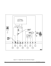
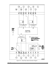
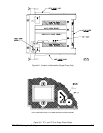
Figure 5-9. Generator Differential Application
Since the three-phase fault is involved, one-way lead burden is used to determine the total CT burden. Each
phase CT carries just the burden for the lead for that phase.
(R
t
)
1
= R
l
+ R
w
= 0.22 + 0.14 = 0.36 ; (Vce)
1
= 50 ; R
t
< 0.007(Vce)
1
= 0.35
(R
t
)
2
= 0.09 + 0.10 = 0.19 ; (Vce)
2
= 100 ; R
t
< 0.007(Vce)
2
= 0.7