BE1-87G - Testing And Setting 5-9
NOTE
Sensing Input Range 1: If R
w
is unknown, assume R
w
= 0.003 * N
a
Sensing Input Range 2: If R
w
is unknown, assume R
w
= 0.01 * N
a
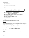
Terms for Calculations
I"
d
Subtransient current
N
Total number of CT turns
N
a
Number of CT turns in use (for multi-ratio type)
R
l
One-way lead resistance, in ohms
R
r
Relay restraint circuit resistance, in ohms
R
w
CT winding resistance, in ohms.
R
t
Total CT burden = R
l
+ R
r
+ R
w
(for phase faults and switching)
= 2R
l
+ 2R
r
+ R
w
(for external ground faults)
SFR
Saturation factor ratio = [(Vce)
1
/(Vce)
2
]*[(R
t
)
2
/(R
t
)
1
] (If SFR is < 1, use 1/SFR)
Vc
CT accuracy-class voltage rating
Vce
Effective CT accuracy-class voltage rating = Vc (N
a
/N)
X"
d
Subtransient reactance
CT Quality
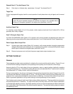
CTs should have an accuracy class of either C20 or better or T20 or better.
Burden Limit
The CTs should be operating below the knee point under symmetrical current conditions --i.e. no "ac saturation".
For a generator, ac saturation should not occur for the maximum external fault current. For a motor, ac
saturation should not occur during starting. For a shunt reactor, high current fundamental-frequency currents
won't flow unless the reactor becomes faulted.
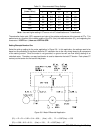
Assuming a maximum current of 20 times CT rating:
R
t
< 0.007Vce (1)
where V
knee
= 70% of Vce and 20 X 5 A nominal rating = 100 A so that
R
t
= V
knee
/ I max = 0.7 Vce/ 100 A = 0.007 Vce
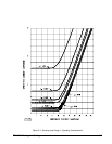
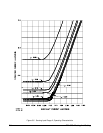
Relative CT Performance
Table 5-1 lists the recommended minimum pickup settings to provide security during external faults and
switching.


