


Servicing Procedures
Introduction
The 734 sprinkler is designed to provide the user trouble-free operation for many years without scheduled maintenance.
Should it become necessary to disassemble the sprinkler to correct a malfunction or replace a component, all internal parts of
the sprinkler are accessible from the top. Refer to the Troubleshooting Procedure in this manual in the event of a malfunction.
Some special tools are required for disassembly and/or maintenance of the sprinkler and are available from your Toro dealer.
Servicing Sprinkler Mechanism
Refer to Toro Illustrated Parts Breakout Book, Form No. 368-0044 for parts identification.
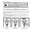
1. Lift Cap using knife blade edge or small screwdriver tip inserted between edge of Cap and Body flange.
2. Grasping edges of Cap, pull sprinkler mechanism up until fully extended.
3. While firmly holding Riser Assembly, remove Cap/Nozzle assembly by turning it counterclockwise. Allow Riser Assembly to
slowly
retract into body.
4. Using two small screwdrivers inserted between Nozzle and Cap, separate Cap from Nozzle Assembly (retained by press fit).
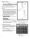
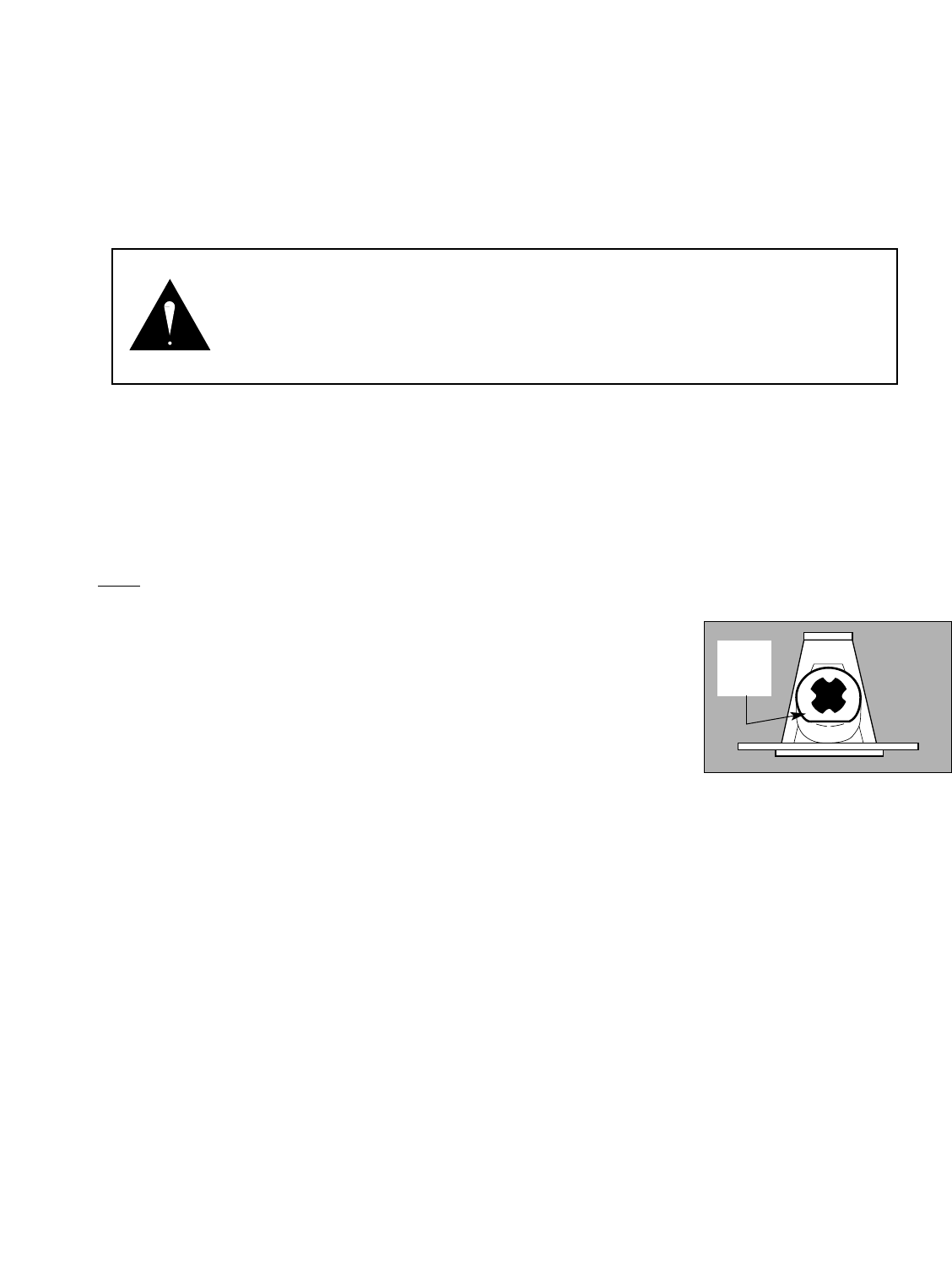
5. To change Nozzles, carefully insert knife blade edge between nozzle flange and base.
Pry nozzle loose and remove. Align new nozzle as shown in illustration at right.
Carefully press new nozzles into Nozzle Base until flange is fully seated.
Avoid contact
with nozzle orifice as sprinkler coverage can be greatly impaired if orifice is damaged
or altered in any way.
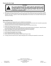
6. Using Multi-Purpose Tool (P/N 995-83) remove Snap Ring from groove in body.
7. Thread Drive Assembly Extraction Tool (995-78) onto drive assembly output shaft and
pull sprinkler assembly out of body.
8. Carefully remove O-ring from top of riser housing.
9. Using Multi-Purpose Tool (P/N 995-83) remove screen by turning it counterclockwise while holding base of riser assembly.
10. Remove Variable Stator.
11. Remove Drive Assembly by pushing against end of threaded output shaft.
12. Inspect Stator Housing for nicks and burrs.
This part can be difficult to remove if sprinkler has been in operation for some time
and should be left in place if it appears undamaged. If replacement is necessary, grasp housing with pliers and pull from riser
housing.
13. Thoroughly clean and inspect all parts. Replace damaged parts as necessary and reassemble in reverse order.
WARNING
TO PREVENT POSSIBLE INJURY DURING SPRINKLER SERVICING PROCEDURES, CON-
FIRM THE FOLLOWING CONDITIONS EXIST PRIOR TO STARTING.
A. WATER SUPPLY TO SPRINKLER IS SHUT OFF AT SOURCE.
B. SYSTEM PRESSURE IS BLED FROM SYSTEM, INCLUDING CONTROL TUBES.
C. A.C. POWER IS DISCONNECTED AT SOURCE.
6
Figure 2
Flat
Spot
Down