


Installation Procedure _____________________
CAUTION
Golf sprinklers are intended for installation at grade with full
support of the body and piping system from the surrounding
earth. Failure to provide full support may result in premature
failure of the body and/or connecting fittings.
To assure maximum performance from your 734 Series Rotary Sprinklers,
read these instructions completely prior to installation or service.
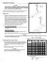
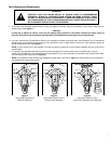
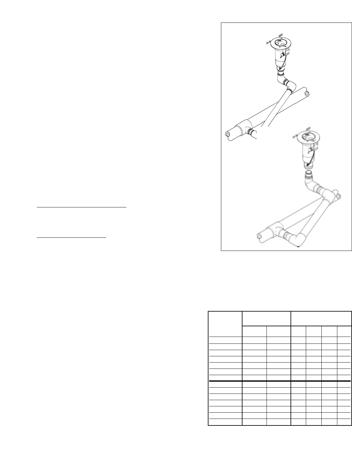
Swing Joints
1. Construct or provide triple swing joints for each sprinkler as shown in
Figure 1. Use PVC or ABS pipe nipple for sprinkler connection.
Note: On sites where the possibility of heavy equipment rolling over a
sprinkler exists, the swing joint will flex preventing damage to the
lateral or main lines. On a new installation in raw ground where the
sprinklers are to be initially installed above the finished grade and
lowered when new turf is established, the swing joint allows sprinkler
repositioning without changing risers. This is a common and practical
procedure which eliminates the problem of dirt being accidentally
introduced into the lateral lines when a riser is changed.
2. Flush lines thoroughly prior to installing sprinkler.
3.
NPT and BSP Threaded Models
• Apply plumbing tape on riser threads. Install sprinkler onto riser
and tighten.
ACME Threaded Models
• Install ACME threaded bodies onto Acme threaded swing joint
by threading clockwise until hand tight
Note: ACME threaded swing joints have an o-ring that seals to the sprinkle. Plumbing tape is not required..
CAUTION
Use only plumbing tape on riser threads. Use of pipe dope or other types of sealing compounds can cause
deterioration of sprinkler body threads.
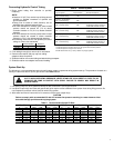
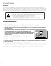
Connecting Electric Control Wires
1. Route control wires to sprinkler location(s). Provide enough extra
wire at sprinkler to allow for movement of sprinkler without straining
wire connections. One common wire and station wire is required
for each sprinkler. See Wire Sizing Chart,
Table 1 for proper
application.
2. Attach control wires to solenoid leads using an approved
waterproof splicing method.
CAUTION
All wires must be waterproofed to prevent short circuit to
ground and subsequent controller damage.
2
VOLTAGE
WIRE NUMBER
AT
SIZE OF VALVES
CONTROLLER
CONTROL COMMON 1 2 3 4
23 V a.c. 14 14 2348 1012 549 353
23 V a.c. 14 12 2890 1239 673 433
23 V a.c. 14 10 3378 1448 786 505
23 V a.c. 12 12 3759 1604 873 561
23 V a.c. 12 10 4591 1973 1071 688
23 V a.c. 12 8 5411 2328 1263 812
23 V a.c. 10 10 5945 2555 1387 892
24 V a.c. 14 14 2765 1309 846 549
24 V a.c. 14 12 3393 1608 1039 673
24 V a.c. 14 10 3962 1877 1213 783
24 V a.c. 12 12 4394 2082 1346 872
24 V a.c. 12 10 5397 2557 1652 1071
24 V a.c. 12 8 6364 3018 1949 1263
24 V a.c. 10 10 6986 3311 2140 1387
Table 1: Wire Sizing Chart
Maximum allowable length in feet from controller to electric VIH
sprinklers.
OUTPUT
VOLTAGE AT
CONTROLLER
TRANSFORMER
Figure 1: Triple Swing Joints
(NPT & BSP
models only)
(ACME
models only)
NOTE: Minimum solenoid voltage required for reliable electric
VIH operation is 20 V a.c.
Chart based on the following
Transformer - 115/230 V a.c. - 24 V a.c., 45 VA
Coil Assy. - 24 Va.c., 60 Hz
Holding - .30 Amps
In Rush - .40 Amps