


Detailed Installation Instructions
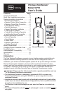
There are two main components of the Wireless RainSensor: the Receiver and
the Sensor/Transmitter. The Receiver is installed adjacent to the irrigation system
controller. The Sensor/Transmitter is installed outdoors where it is exposed to
unobstructed rainfall.
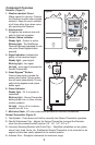
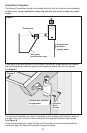
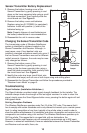
Mounting the Receiver
1. Mount the Receiver FIRST, adjacent to the controller with either the provided stain-
less steel screws or double-sided foam tape. The connection wire cable is 20"
long, so before attaching the Receiver, make sure the wires will easily reach the
controller’s connection terminals.
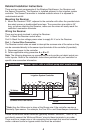
Wiring the Receiver
There are two parts involved in wiring the Receiver:
Part 1: Attach the Receiver control wires.
Part 2: Attach the low-voltage power wires to supply 24 V ac to the Receiver.
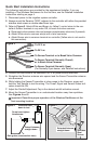
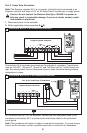
Part 1 - Control Wire Connection
The Receiver control wires are used to interrupt the common wire of the valves or they
can be connected directly to the sensor input terminals of the controller (if provided).
1. Disconnect power to the controller.
2. Follow applicable wiring procedure A or B or C.
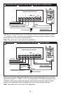
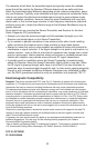
Note: The following diagrams are representations only and do not depict actual con-
troller layouts. Refer to the installation instructions provided with your controller for
specific wire connection information.
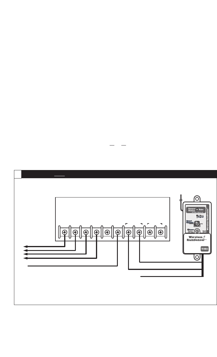
Locate the controller sensor terminals (generally marked “SENSOR”, “SEN” or “S”)
and directly connect the White and Brown* wires to these terminals in any order.
There may be a jumper wire or tab connecting the terminals that must be removed
and/or a sensor control or bypass switch that must be activated.
4
SENSOR
COM
PUMP/
MV
24 VAC
21
34
Brown
*
Common Wire From Valves
To Valves
Irrigation System Controller
White
Yellow*
*
Note: Use the Yellow wire in place of the Brown wire if the controller requires a
Normally Open sensor. For example, the Toro ECx
TM
and GreenKeeper
®
controllers.
Controllers with sensor inputs , with or without pump start /master valve:
A