


Component Overview
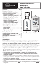
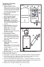
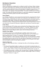
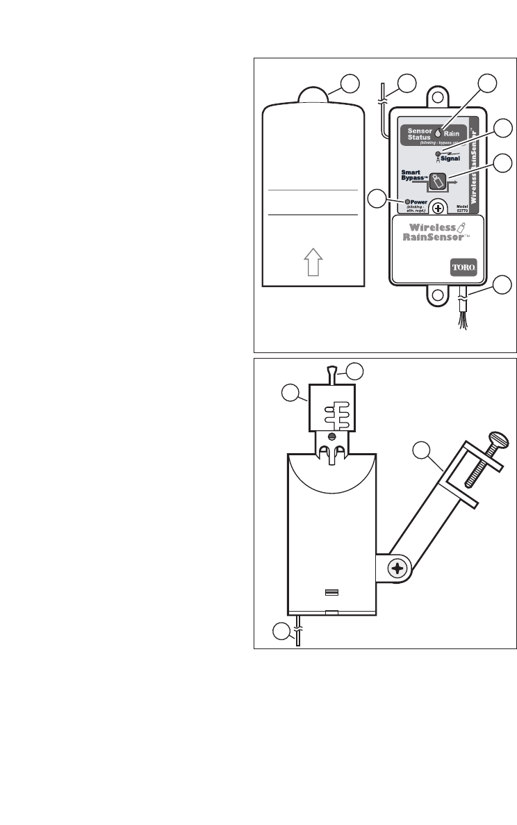
Receiver (Figure 1)
1- Weather-resistant Cover:
Slides upward to remove. Protects
the Receiver module when located
outdoors. Keep the cover installed
at all times other than when manu-
ally operating the Receiver.
2- Antenna wire:
Straighten the antenna wire verti-
cally for the best reception.
3- Sensor Status Indicator:
Steady light
- Sensor is active.
Blinking light - The RainSensor
Receiver has been bypassed for one
rain cycle (Smart Bypass button
pressed).
4- Signal Indicator: Indicates the
quality of last received signal.
Steady light - good signal.
Blinking light - fair signal.
No light - poor signal (relocate the
Sensor/Transmitter).
5- Smart Bypass
TM
Button:
Press to temporarily override the
sensor when active. Sensor opera-
tion will reset automatically. To man-
ually exit the bypass mode, press
button again.
6- Power Indicator:
Steady light
- 24 V ac power is
connected.
Blinking light - Sensor/Transmitter
battery power low, or other commu-
nication problem.
No light - Unit is off or is discon-
nected from 24 V ac.
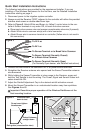
7 - Multi-wire Cable - 20" color-coded wires provided for controller connections.
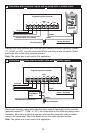
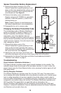
Sensor/Transmitter (Figure 2)
1-
Test Spindle - Press down and hold to manually test Sensor/Transmitter operation.
2- Rainfall Adjustment Cap - Adjusts the Sensor/Transmitter to signal the Receiver
when the accumulated rainfall reaches 1/8", 1/4", 1/2", 3/4" or 1".
3- Universal Mounting Bracket with Quick-Clip
TM
- Simplifies installation on rain gutter,
side of roof, shed, fence, etc. Enables the Sensor/Transmitter to be mounted on an
angled surface then easily adjusted to the vertical position.
4- Antenna Wire - Straighten downward for maximum range.
2
1
3
4
5
6
7
2
1
2
3
4
Figure 1
Figure 2