


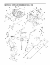
SECTION7: SERVICINGYOURSNOWTHROWER
WARNING: Before servicing, repairing, or
inspecting, disengage all controls and
stop engine. Wait until all moving parts
have come to a complete stop. Disconnect
spark plug wire and ground it against the
engine to prevent unintended starting.
Always wear safety glasses during
operation or while performing any
adjustments or repairs.
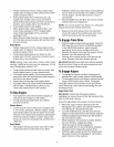
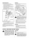
Augers
• The augers are secured to the spiral shaft with four
(Model 1028) or six (Model 1130) shear pins and
cotter pins. If you hit a hard foreign object or ice
jam, the snow thrower is designed so that the bolts
may shear. Refer to Figure 15.
• If the augers will not turn, check to see if the pins
have sheared. Replacement shear pins and cotter
pins have been provided with the snow thrower.
When replacing pins, spray an oil lubricant into
shaft before inserting new pins.
IMPORTANT:NEVER replace the auger shear pins with
standard pins. Any damage to the auger gearbox or
other components as a result of doing so will NOT be
covered by your snow thrower's warranty.
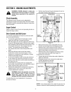
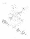
ShavePlateandSkidShoes
• The shave plate and skid shoes on the bottom of
the snow thrower are subject to wear. They should
be checked periodically and replaced when
necessary.
• Remove the carriage bolts and flange lock nuts
which attach the two skid shoes to the snow thrower
on two sides. See Figure 12.
• Reassemble new skid shoes with the hardware
removed earlier. Make certain the skid shoes are
adjusted to be level.
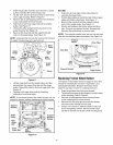
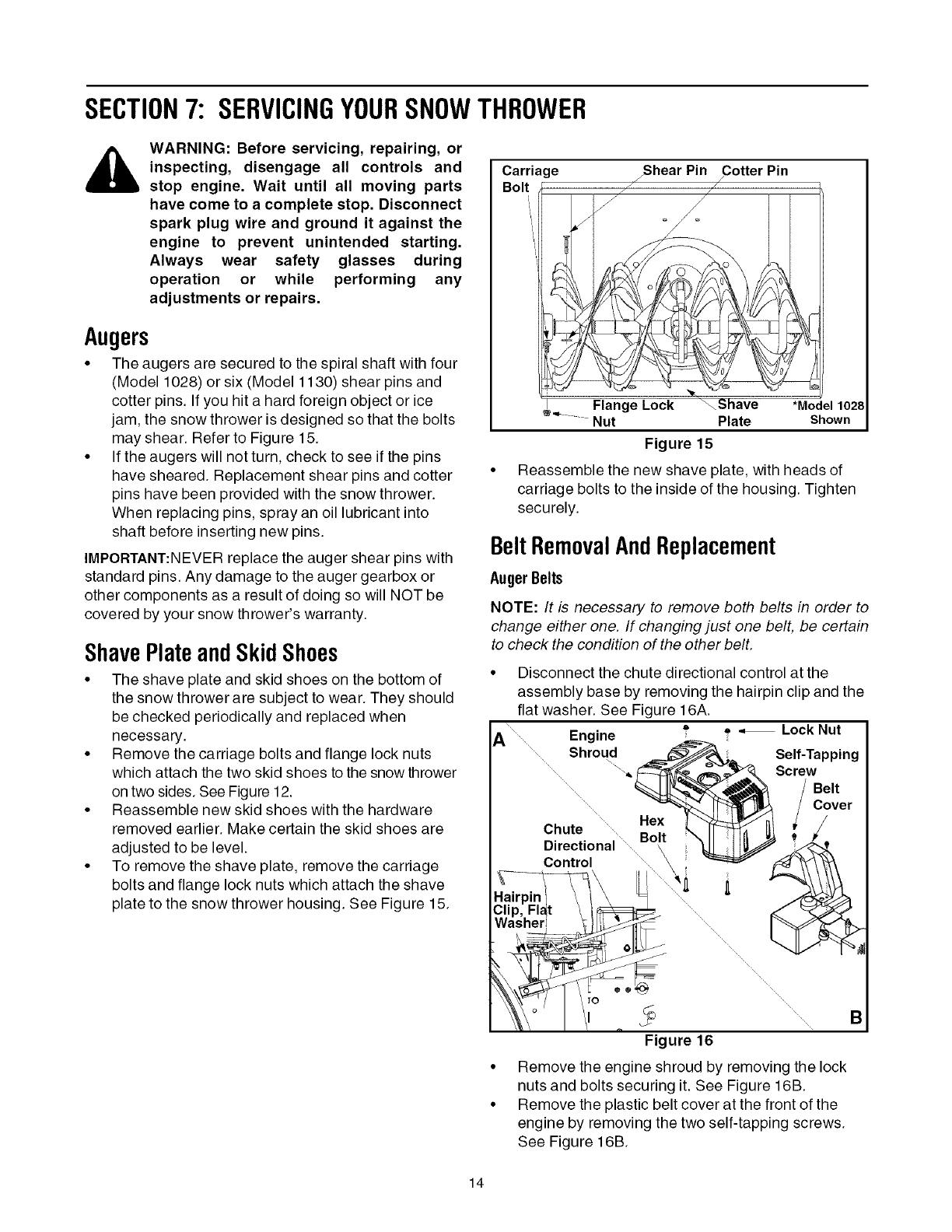
• To remove the shave plate, remove the carriage
bolts and flange lock nuts which attach the shave
plate to the snow thrower housing. See Figure 15.
Carriage
/Shear Pin Cotter Pin
/ /
/ /
Flange Lock _Shave *Model1028
Nut Plate Shown
Figure 15
Reassemble the new shave plate, with heads of
carriage bolts to the inside of the housing. Tighten
securely.
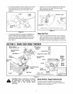
BeltRemovalAndReplacement
AugerBelts
NOTE: It is necessary to remove both belts in order to
change either one. If changing just one belt, be certain
to check the condition of the other belt.
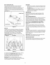
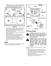
• Disconnect the chute directional control at the
assembly base by removing the hairpin clip and the
flat washer. See Figure 16A.
A Engine = o _, Lock Nut
........ Shroud _,= Self-Tapping
......... \/_./_ ,,_v_ Screw
........... _'_Y_!_ / Belt
......... / Cover
..... Hex
Chute ..... Hex L__/ , J
..... Bolt \11 IHI _ _"
ulrecuonal \ _--_1 _ .._<_,t,
Control ........_ \ i _ _:_
Hairpin i \ t \ =t ....... /f_v_
Clip, Flat / tf_ ....... _'_
Figure 16
• Remove the engine shroud by removing the lock
nuts and bolts securing it. See Figure 16B.
• Remove the plastic belt cover at the front of the
engine by removing the two self-tapping screws.
See Figure 16B.
14