Assembly Section 2-19
ASSEMBLY
DECK ATTACHMENT
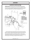
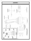
Attach the head to the secondary boom using the pins and hardware shown in the
parts section to attach linkages. Install the square tube on the top of the head into
the head mount and secure using the mounting plate and hardware as shown. The
mount should be positioned to the left side of the cutter head. Install the deck pivot
cylinder using the pins and hardware also shown in the parts section.
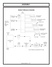
Connect the fittings and hoses from the pivot cylinder to the small preformed
tubes on the boom arm. Connect the fittings and hoses from the motor to the large
preformed tubes on the boom arm.
Connect all remaining hoses from the control valve to the cylinders and / or
preformed tubes on the boom arm. Refer to parts section for diagrams.
Before proceeding to the final preparation step double check the
complete assembly from the main frame to the cutter head against the
diagrams in the parts section for proper placement and assembly of all
components.
BOOM INSTALLATION
Install the boom swivel into the main frame as shown in the parts section using a
hoist. Line up holes in swivel and main frame for large swivel pin and insert pin.
Secure with hardware as shown.
Attach the inner end of the main boom to the boom swivel using pins and
hardware as shown. Be sure that the bearings are properly installed as shown in
the boom parts section.
Install main boom cylinder on the main boom with the fittings facing towards the
rear of the tractor. Attach the butt end to the main boom cylinder to the swivel
bracket anchor with cylinder pin and hardware shown in parts section. Attach the
piston clevis to the main boom with the cylinder pin and hardware. Install all fittings
into the cylinders and hoses as shown in the boom and lift valve parts sections.
NOTE: Be sure to use teflon tape on all pipe fittings (except O-rings).
HOSE COVERING
Secure hoses together with zip ties wherever loose. Wrap the hoses between
the main boom and secondary boom with the yellow hose cover, secure with black
string provided. Where hoses may contact the frame or other edges, wrap with split
hose and secure with hose clamps or zip ties. On non cab units the pressure and
return hoses from the control valve will also need to be routed inside the protective
clear hose wrap. Cover the valve, valve fittings with the yellow hose cover and
secure with black string provided.
PREFORMED TUBE INSTALLATION
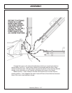
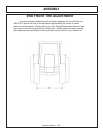
Place the booms on the floor so that side with weldnuts is upward. If mounting a
ditcher head, only the main boom tube installation is required. Locate all tube
clamps and install them loosely in the welded nuts on the left side of the booms.
Arrange the tubes and hoses as outlined in the parts section diagram. Install the
smaller tube closest to the boom arm, being careful nut to pinch the tubes. Place
the large tubes outside of the small tubes. Snug all clamp bolts, but do not tighten.
Check all tubes for correct alignment and that none are pinched or bent. The clamp
bolts can now be tightened.


