


www.tanaka-usa.com 4 custsvc@tanaka-ism.com
Owner’s Manual
TPS-2501,TPS-2510.TPS-250PN,TPS-270PN
3. Assembly procedures
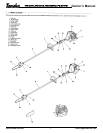
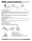
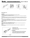
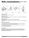
Drive shaft to engine (Fig. 1 -1)
Loosen tube locking bolt (1) about ten turns so that the bolt point will not obstruct drive shaft tube to be inserted. When
inserting drive shaft tube, hold the tube locking bolt outward preventing inside fitting from obstructing as well.
Insert the drive shaft into the clutch case of the engine properly until the marked position (2) on the drive shaft tube
meets the clutch case.
NOTE!
When it is hard to insert drive shaft up to the marked position on the drive shaft tube, turn drive shaft by the cutter
mounting end clockwise or counterclockwise. Tighten tube locking bolt lining up the hole in the shaft tube.
Then tighten clamp bolt securely (3).
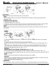
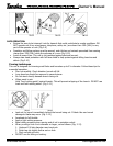
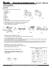
Cutting attachment to drive shaft (Fig. 1-2)
Loosen tube locking bolt (1).
Insert the drive shaft into the gear case of the attachment properly until the marked position (2) on the drive shaft tube
meets the gear case.
NOTE!
When it is hard to insert drive shaft up to the marked position on the drive shaft tube, turn attachment clockwise or
counterclockwise.
Tighten tube locking bolt lining up the hole in the shaft tube.
Then tighten clamp bolt securely (3).
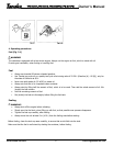
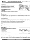
Installation of handle (Fig. 1-3)
Attach the handle to the drive shaft tube with the angle towards the engine.
Adjust the location to the most comfortable position before operation.
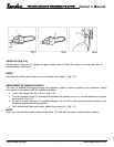
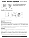
Throttle wire/stop cord
Remove air cleaner cover. (Fig. 1-4)
Connect stop cords. (Fig.1 -5)
Connect throttle wire end to carburetor. (Fig. 1 -6)
Cover throttle wire and stop cords together with protective tube
provided up to air cleaner cover. (Fig. 1 -7)