


tanaka-usa.com 5 custsvc@tanaka-ism.com
Owner’s Manual
TS-720 E-Z Tiller™
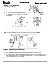
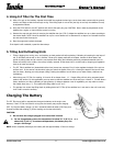
3. Connecting The Throttle Linkage
a. (FIG. 7) Slide the throttle wire through the cable
adjuster (2). Line up the "slotted" swivel (3) with the
wire, making sure the hole for the wire end is opposite
the cable adjuster. (See arrow.)
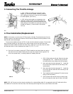
b. (FIG. 8) Once the throttle wire is attached to the
carburetor, locate the other end of the throttle wire
and insert the wire end (2) into the throttle lever hole.
While pulling on the throttle wire (outer part) insert the
throttle wire sleeve (1) -into the hole in the throttle
lever (3).
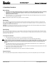
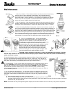
4. Tine Installation/Replacement
NOTE: In this section, we refer to the E-Z Tiller’s right or left side. These directions are from the
operator’s point of view behind the machine. All four tines are different and their positions on the
shaft should not be interchanged.
Tines must be installed as shown in FIG. 9 or the unit will not function property. The two outer
tines have teeth pointing in one direction only, while the teeth of the inner tines point both
outward and inward. Notice that each tine has a heavy, metal hub on one side, near the center.
And that each side of a tine is stamped with a letter "A", "B", "C", or "D".
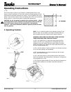
a) On a level, firm surface, grasp the E-Z Tiller’s handle bars and pivot them over and on
the other side of the engine. Gently lower the top of the engine onto the ground. The
unit is now upside down, in a handy position for installing the tines.
b)
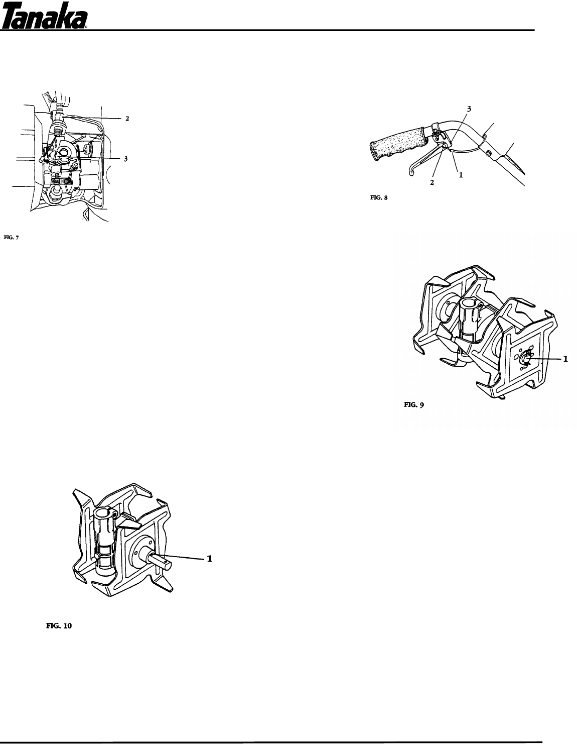
1. (FIG. 10) Start with the left side. Select the tine that
is stamped with a "B". Install the tine (on the left
tine shaft) with the hub facing to the left (outward).
2. Next, select the tine that is stamped "A". Install this
tine on the left tine shaft with the hub facing to the
right (inward).
3. Next, select the tine that is stamped "C". Install this
tine on the right tine shaft with the hub facing to the
right (outward).
4. Then install the last tine (stamped "D") with the hub
facing to the left (inward).
5. (FIG. 9) Secure both sets of tines by inserting snap
pins (1) through the outer sets of holes in the shaft.
NOTE. (FIG. 10) The two inner tines may be used alone for a reduced tilling width (6"), as opposed to the full 9" width with all four
tines attached. To secure the two inner tines, insert the snap pins through the inner (1) set of holes in the shaft.