8
Assembling the Outer Tube
NOTE:
Make sure that the throttle cable
is built into the cable guide of the
throttle lever.
(8) Shift the throttle lever back to original
position, pulling the ground wire and
throttle cable and tighten the screw
securely.
(9) Remove the bolt tightening the cylinder
cover.
(10) Put the bolt through the hole of the
ground wire terminal and tighten the
bolt.
Assembly of the Outer Tube
C350/B450
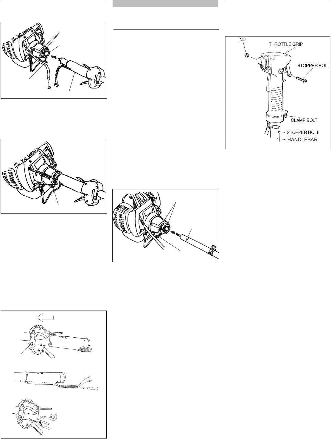
(4) Loosen the stopper bolt of the throttle
grip. Remove the stopper bolt and nut.
(5) Fully loosen the clamp bolt of the
throttle grip.
(6) Slip the right-side handlebar into the
throttle grip. Locate the throttle grip so
that the stopper bolt can pass through
the stopper hole.
Securely tighten the stopper bolt and
nut.
(7) Securely tighten the clamp bolt.
T350
(1) Loosen the 2 joint bolts fully.
JOINT BOLT
JOINT
GROUND WIRE
THROTTLE GRIP
(2) Slip the outer tube into the joint until
the tube bottoms. The outer tube or
gearcase shaft may have to be rotated
slightly for the splines on the mainshaft
to fully engage to the engine.
GROUND WIRE
(3) Attach the ground wire to the joint bolt.
(4) Tighten the 2 joint bolts securely.
(5) Loosen the screw which tightens the
throttle lever to the outer tube. Shift the
throttle lever toward the blade.
(6) Put the throttle cable into the tube.
Push throttle cable through hole in
rear grip.
(7) Set the throttle cable onto the
throttle lever. Use the wrench so
that the wire edge goes into the slot
of the throttle lever securely.
(1) Loosen the 2 joint bolts fully and slip
the outer tube into the joint until the
tube bottoms (up to the insert label).
The outer tube or gearcase shaft may
have to be rotated slightly for the splines
on the mainshaft to fully engage the
engine.
(2) Attach the ground wire to the joint bolt.
(3) Tighten the 2 joint bolts securely.
GROUND WIRE
JOINT BOLT
INSERT LABEL
SCREW


