


65
ENGLISH
EN
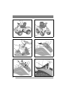
same pressure and can follow the contours of the
ground.
Use the floating position when carrying out work.
Lowering. The implement lowers re-
gardless of its weight.
Locking in the transport position. The
lever has returned to the neutral position
after raising and lowering. The imple-
ment is locked in the transport position.
Raising. Move the lever to the rear posi-
tion until the implement is in the highest
position (transport position). Then re-
lease the lever to lock in the transport po-
sition.
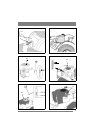
2.4.3 Clutch-parking brake (3:B)
Never press the pedal while driving.
There is a risk of overheating in the
power transmission.
The pedal (3:B) has the follow-
ing three positions:
• Released. The clutch is not activated. The park-
ing brake is not activated.
• Depressed halfway. Forward drive disengaged.
The parking brake is not activated.
• Pressed down. Forward drive disengaged. The
parking brake is fully activated but not locked.
•
2.4.4 Inhibitor, parking brake (3:A)
The inhibitor locks the “clutch-brake”
pedal in the depressed position. This func-
tion is used to lock the machine on slopes,
during transport, etc., when the engine is
not running.
Locking:
1. Depress the pedal (3:B) fully.
2. Move the inhibitor (3:A) to the right.
3. Release the pedal (3:B).
4. Release the inhibitor (3:A).
Unlocking:
Press and release the pedal (3:B).
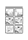
2.4.5 Driving-service brake (3:F)
The pedal (3:F) determines the gearing ratio be-
tween the engine and the drive wheels (= the
speed). When the pedal is released, the service
brake is activated.
1. Press the pedal forward –
the machine moves forward.
2. No load on the pedal – the ma-
chine is stationary.
3. Press the pedal backward –
the machine reverses.
4. Reduce the pressure on the
pedal – the machine brakes.
There is an adjustment plate on the upper section
of the pedal. The adjustment plate can be adjusted
to three (3) positions to suit the driver’s foot.
2.4.6 Steering wheel (3:D)
The height of the steering wheel is infinitely ad-
justable. Undo the adjustment knob (3:E) on the
steering column and raise or lower the steering
wheel to the desired position. Tighten.
Do not adjust the steering wheel during
operation.
Never turn the steering wheel when the
machine is stationary with a lowered
implement. There is a risk of abnormal
loads on the servo and steering mecha-
nisms.
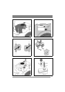
2.4.7 Throttle control (4,5:G)
Control for setting the engine’s revs.
1. Full throttle – when the machine is in
operation, full throttle should always be
used.
2. Idling.
2.4.8 Choke control (4,5:H)
A pull-type control to choke the engine when start-
ing from cold.
1. Control fully pulled out – choke valve
in carburettor closed. For starting cold en-
gine.
2. Control pushed in – choke valve open.
For starting warm engine and when oper-
ating the machine.
Never operate the machine with the choke
pulled out when the engine is warm.