


64
ENGLISH
EN
1 GENERAL
This symbol indicates WARNING. Seri-
ous personal injury and/or damage to
property may result if the instructions
are not followed carefully.
You must read these instructions for use
and the accompanying pamphlet
“SAFETY INSTRUCTIONS” careful-
ly, before starting up the machine.
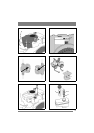
1.1 SYMBOLS
The following symbols appear on the machine.
They are there to remind you of the care and atten-
tion required during use and maintenance.
This is what the symbols mean:
Warning!
Read the instruction manual and the safety
manual before using the machine.
Warning!
Watch out for discarded objects. Keep on-
lookers away.
Warning!
Always wear hearing protectors.
Warning!
This machine is not designed to be driven
on public roads.
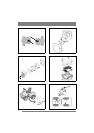
Warning!
The machine, equipped with original ac-
cessories, must not be driven in any direc-
tion on slopes with a gradient greater than
10º.
Warning!
Risk of crushing injuries. Keep hands and
feet well away from the articulated steer-
ing joint.
Warning!
Risk of burn injuries. Do not touch the si-
lencer/catalytic converter.
1.2 References
1.2.1 Figures
The figures in these instructions for use are num-
bered 1, 2, 3, etc.
Components shown in the figures are marked A, B,
C, etc.
A reference to component C in figure 2 is written
“2:C”.
1.2.2 Headings
The headings in these instructions for use are num-
bered in accordance with the following example:
“1.3.1 General safety check” is a subheading to
“1.3 Safety checks” and is included under this
heading.
When referring to headings, only the number of the
heading is normally specified. E.g. “See 1.3.1”.
2 DESCRIPTION
2.1 Drive
The machine has 4-wheel drive. The power from
the engine to the drive wheels is transferred hy-
draulically. The engine drives an oil pump, which
pumps oil through the rear and front axle drives.
The front axle and rear axle are connected in se-
ries, which means that the front wheels and rear
wheels are forced to rotate at the same speed.
To make turning easier, both axles are equipped
with differential.
Front-mounted implements are powered via drive
belts.
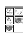
2.2 Steering
The machine is articulated. This means that the
chassis is divided into a front and a rear section,
which can be turned in relation to each other.
The articulated steering means that the machine
can turn around trees and other obstacles with an
extremely small turning radius.
2.3 Safety system
The machine is equipped with an electrical safety
system. The safety system interrupts certain activ-
ities that can entail a danger of incorrect manoeu-
vres. For example, the engine cannot be started if
the clutch-parking brake pedal is depressed.
The operation of the safety system must
always be checked every time before
use.
2.4 Controls
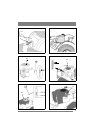
2.4.1 Implement lifter, mechanical (3:C)
(Pro16)
To switch between working position and transport
position:
1. Depress the pedal fully.
2. Release the pedal slowly.
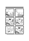
2.4.2 Implement lifter, hydraulic (5:M)
(Pro20, Pro25, Pro Svan)
The hydraulic implement lifter only works when
the engine is running and the clutch pedal and
parking brake pedal are not depressed. The imple-
ment lifter is controlled using the lever (5:M).
The lever has the following four positions:
Floating position. Move the lever to its
front position, where it locks. The imple-
ment is now lowered to its floating posi-
tion.
In the floating position, the implement
always rests against the ground at the