


ENGLISH
EN
• Always keep at a safe distance to the rotors when wor-
king.
• Holding the steering correctly ensures a safe distance.
• No person must come closer than 20 m to the machine
when working on slopes. The user must hold the steering
firmly with both hands all the time.
• Working on stony or hard ground demands extra attention
from the operator. The machine becomes more unstable.
• Never touch the engine when operating the machine, or
just afterwards. Risk for burn injuries.
2.4 AFTER OPERATING
• Allow the engine to cool before putting the machine in a
storeroom. Fire risk!
• Remove dirt and foreign material before putting the ma-
chine in a storeroom. The area round the petrol tank and
muffler must be kept clean from leaves, oil, petrol or
other foreign materials. Fire risk!
• If the petrol tank is to be emptied, do this outdoors and
when the engine is cold. Fire risk!
• The machine should be stored in a dry place. The machi-
ne must not stored with fuel in the tank in rooms where
there are naked flames, sparks or other strong sources of
heat.
2.5 MAINTENANCE
• Carry out maintenance regularly. All nuts and bolts
should always be tight.
• Only use genuine spare parts which are in good conditi-
on. Spare parts must not be repaired. They must be repla-
ced if they are defective. Poor quality spare parts can lead
to personal injury. If the muffler is damaged it must be re-
placed.
• The engine must be stopped and the spark plug lead dis-
connected in the following circumstances:
When adjusting the rotors.
When the machine is to be cleaned or repaired. When
checking after a collision with a solid hard object. Carry
out the necessary repairs before continuing to work.
If the machine begins to vibrate abnormally. Carry out
the necessary repairs before continuing to work.
• Wear protective gloves when working with the rotors.
3 DELIVERY
The tiller is delivered in a box with the steering and side pla-
tes dismantled. All the wires are fitted and adjusted.
WARNING! There is no oil in the engine on
delivery.
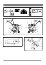
4 DESCRIPTION, SEE FIG. 2
The tiller is driven by a four-stroke engine and consists of the
following parts:
1. Clutch control, activation of the blades
2. Gear control, forward/reverse
3. Steering adjuster
4. Air filter
5. Manual start
6. Splashguard
7. Tail brake
8. Data plate
9. Side roller
10. Throttle control
11. Fuel tank
12. Oil filler
13. Oil plug
14. Support wheel
15. Rotors, 4, the outer rotors can be removed. The working
width then becomes 340 mm
16. Cover
17. Cover for muffler
18. Exhaust
19. Handle
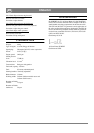
The data plate (8) contains the following information.
See fig. 3.
A Nominal power
B Weight in kg
C Serial number
D Year of manufacture
E Type F Manufacturer
G CE-mark
H Max. engine speed
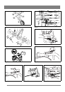
5 ASSEMBLY
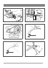
5.1 STEERING, SEE FIG. 4
Fit the steering (1) according to the figure with the bolt (2),
washer (3), nut (4), bolt (5), washer (6) and nut (7). Choose
a suitable hole for the bolt (5) for comfortable adjustment of
the steering (1).
5.2 SPLASHGUARD, SEE FIG. 2
Fit the splashguards (6) on both sides with the enclosed nuts
and bolts.