


ENGLISH
EN
3.2 Installation of 107 M HD, 121 M
1. Place the cutting deck in position in front of the
machine.
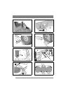
2. Install the following components on both wheel
axles:
• Washer (3:B).
• Deck mount (3:C).
• Washer (3:B).
• Circlip (3:A).
3. Remove the pins on both sides. See fig. 7:I and
fig. 13.
4. Screw the arms into each other. See fig. 4.
5. Suspend the cutting deck in the implement lift-
er. See fig. 14.
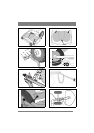
6. If the deck has electrical cutting height adjust-
ment, connect the cable to the machine’s front
right socket. See fig. 15.
3.2.1 Belt, 107 M HD, 121 M
The cutting deck’s rear section should rest on the
floor (it should not be lifted or secured).
Install the belt as follows:
1. 107 M HD
: Set the maximum cutting height.
121 M
: Set the cutting height in the centre posi-
tion
2. Remove the belt cover. See fig. 8 and 10. The
number in the figure indicates the key width.
3. Locate the belt around the machine’s belt pulley
(16:M).
4. Force the belt onto the cutting deck’s belt pul-
ley.
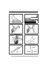
5. Grip the belt tensioner’s lever with your left
hand. Pull the lever and apply the tensioner to
the outside of the belt with your right hand. See
fig. 16.
6. Fit the belt cover. See fig. 8 and 10.
7. Lift up and secure the rear section of the cutting
deck.
107 M HD on machines with 17” wheels:
Install
the pins in the third hole from the top. See fig.
13.
107 M HD on machines with 16” wheels:
Install
the pins in the fourth hole from the top. See fig.
13.
121 M: Lift up and install the pins (7:I).
3.3 Installing 107 M
1. Place the cutting deck in position in front of the
machine.
2. Install the following components on both wheel
axles:
• Washer (11:B).
• Deck arm (11:D).
• Washer (11:B).
• Circlip (11:A).
3. Install the deck arms in the cutting deck’s front
corners. After tightening, it should be possible
to move the rear section of the cutting deck free-
ly up and down.
4. Suspend the cutting deck in the implement lift-
er. See fig. 14.
3.3.1 Belt, 107 M
The cutting deck’s rear section should rest on the
floor (it should not be lifted or secured).
Install the belt as follows:
1. Set the maximum cutting height.
2. Remove the belt cover. See fig. 10. The number
in the figure indicates the key width.
3. Locate the belt around the machine’s belt pulley
(16:M).
4. Force the belt onto the cutting deck’s belt pul-
ley.
5. Grip the belt tensioner’s lever with your left
hand. Pull the lever and apply the tensioner to
the outside of the belt with your right hand. See
fig. 16.
6. Fit the belt cover. See fig. 10.
7. Lift up the cutting deck so that it locks in the
catches (12:L).
3.4 Tyre pressure
Adjust the air pressure in the tyres as follows:
Front: 0.6 bar (9 psi).
Rear: 0.4 bar (6 psi).
3.5 Basic setting
In order for the cutting deck to cut optimally, the
correct basic setting is required. The deck is in the
basic setting when its rear edge is 5 mm above its
front edge. This means that the deck is inclined
forwards.
Carry out basic setting as described below.
3.5.1 Basic setting, 125 Combi Pro, 107 M
HD
The deck is in the basic setting when the actions
under 3.1.1 and 3.2.1 have been carried out.
3.5.2 Basic setting, 107 M, 121 M
See fig. 17 and perform basic setting of 107 M and
121 M as follows:
1. Place the machine on a level floor.
Requirements for floor flatness: ±1 mm/m. No
slope towards a floor drain or similar may occur
in front of or behind the machine.
2. The tyres must have the correct air pressure.
See 3.4.
3. Place the deck in transport position and lay a
plane-parallel plank under the deck.
4. Place a 5 mm tall spacer on the plank under the
rear edge of the cutting deck, and lower the
deck to the working position.