


ENGLISH
EN
1 GENERAL
This symbol indicates WARNING. Seri-
ous personal injury and/or damage to
property may result if the instructions
are not followed carefully.
You must read these instructions for use
and the machine’s safety instructions
carefully.
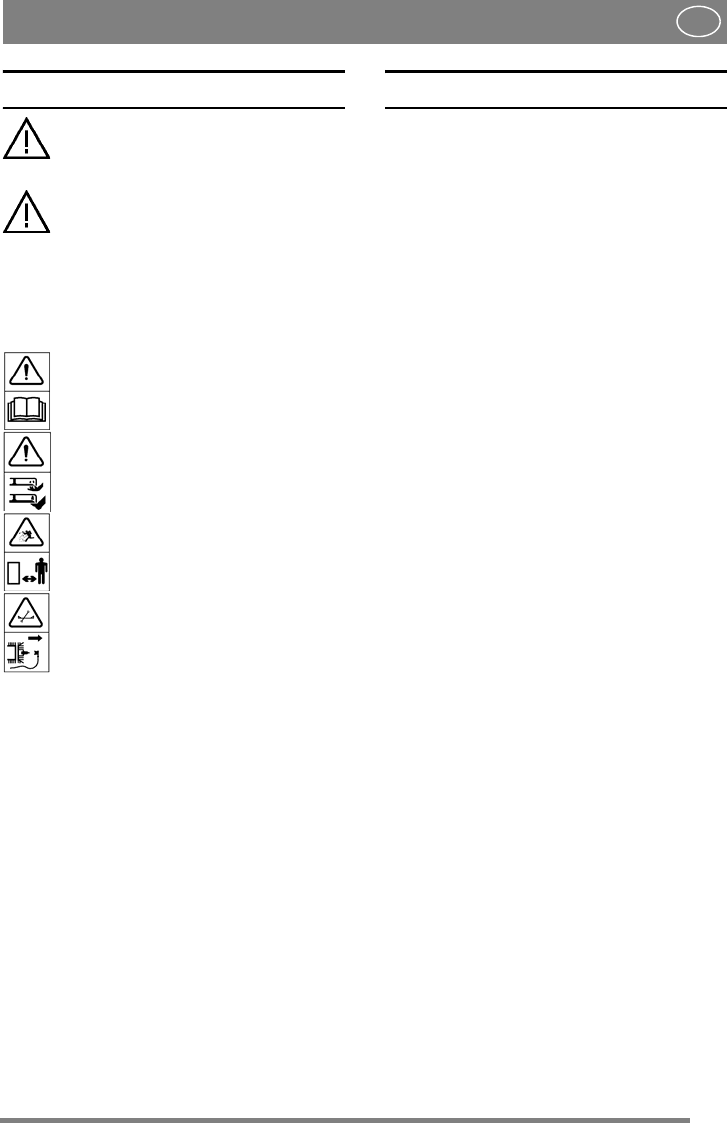
1.1 Symbols
The following symbols appear on the machine.
They are there to remind you of the care and atten-
tion required in use.
This is what the symbols mean:
Warning!
Read the instruction manual and the safety
manual before using the machine.
Warning!
Do not insert your hands or feet under the
cover when the machine is in operation.
Warning!
Watch out for discarded objects. Keep on-
lookers away.
Warning!
Before starting repair work, remove the
spark plug cable from the spark plug.
1.2 References
1.2.1 Figures
The figures in these instructions for use are num-
bered 1, 2, 3, etc.
Components shown in the figures are marked A, B,
C, etc.
A reference to component E in figure 5 is written
“5:E”.
1.2.2 Headings
The headings in these instructions for use are num-
bered in accordance with the following example:
“2.3.2” is a subheading to “2.3” and is included un-
der this heading.
When referring to headings, only the number of the
heading is normally specified. E.g. “See 2.3.2”.
2 DESCRIPTION
2.1 General
The cutting deck is intended for use on Stiga’s 4-
wheel drive Park machines.
The cutting deck is supplied in one of the follow-
ing versions:
• With manual adjustment of cutting height.
• With electrical adjustment of cutting height.
2.2 Controls, 125 Combi Pro
2.2.1 Cutting height adjustment
The cutting height can be adjusted between 25 and
90 mm.
Electrical cutting height adjustment
The setting can be adjusted infinitely variably us-
ing a switch on the machine.
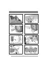
Manual cutting height adjustment
The setting can be adjusted to a number of fixed
positions using the lever. See fig. 1.
2.2.2 Incline forwards
The rear section of the cutting deck can be raised
12 mm by moving the two pins down one hole
from the basic setting. See fig. 2.
2.2.3 Rear mounting
The cutting deck’s rear section is secured with the
pins in fig. 2.
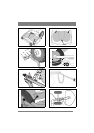
2.2.4 Mounting in implement lifter
The deck is mounted in the implement lifter with a
chain and snap hooks.
One snap hook is intended for the working position
and can be moved in the chain links to set the lift-
ing force.
The other snap hook is intended for the washing
position.
2.3 Controls, 107 M HD
2.3.1 Cutting height adjustment
The cutting height can be adjusted between 30 and
85 mm.
Electrical cutting height adjustment
The setting can be adjusted infinitely variably us-
ing a switch on the machine.
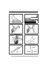
Manual cutting height adjustment
The setting can be adjusted to a number of fixed
positions using the lever. See fig. 9.
2.3.2 Incline forwards
The rear section of the cutting deck can be raised
12 mm by moving the two pins down one hole
from the basic setting. See fig. 13.