


ENGLISH
EN
2.3.3 Rear mounting
The cutting deck’s rear section is secured with the
pins in fig. 13.
2.3.4 Mounting in implement lifter
The deck is mounted in the implement lifter with a
chain and snap hooks.
One snap hook is intended for the working position
and can be moved in the chain links to set the lift-
ing force.
The other snap hook is intended for the washing
position.
2.4 Controls, 107 M
2.4.1 Cutting height adjustment
The cutting height can be adjusted between 30 and
85 mm.
The setting can be adjusted to a number of fixed
positions using the lever. See fig. 9.
2.4.2 Incline forwards
The cutting deck’s rear section can be raised infi-
nitely variably.
Each line (12:J) corresponds to a raise of 5 mm.
The setting is locked with the screws (12:K).
2.4.3 Rear mounting
The cutting deck’s rear section is secured with the
catches (12:L).
2.4.4 Mounting in implement lifter
The deck is mounted in the implement lifter with a
chain and snap hooks.
One snap hook is intended for the working position
and can be moved in the chain links to set the lift-
ing force.
The other snap hook is intended for the washing
position.
2.5 Controls, 121 M
2.5.1 Cutting height adjustment
The cutting height can be adjusted between 30 and
85 mm.
Electric cutting height adjustment
The setting can be adjusted infinitely variably us-
ing a switch on the machine.
Manual cutting height adjustment
The setting can be adjusted to a number of fixed
positions using the lever (7:G).
2.5.2 Incline forwards
The cutting deck’s rear section can be raised infi-
nitely variably.
The setting is locked with the screws (7:H).
2.5.3 Rear mounting
The cutting deck’s rear section is secured with the
pins (7:I).
2.5.4 Mounting in implement lifter
The deck is mounted in the implement lifter with a
chain and snap hooks.
One snap hook is intended for the working position
and can be moved in the chain links to set the lift-
ing force.
The other snap hook is intended for the washing
position.
3 ASSEMBLY
3.1 Installing the 125 Combi Pro
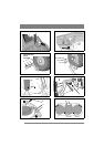
1. Place the cutting deck in position in front of the
machine.
2. Install the following components on both wheel
axles:
• Washer (3:B).
• Deck mount (3:C).
• Washer (3:B).
• Circlip (3:A).
3. Remove the pins and the washers on both sides.
See fig. 2.
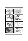
4. Screw the arms into each other. See fig. 4.
5. Suspend the cutting deck in the implement lift-
er. See fig. 14.
6. If the deck has electrical cutting height adjust-
ment, connect the cable to the machine’s front
right socket. See fig. 15.
3.1.1 Belt, 125 Combi Pro
The cutting deck’s rear section should rest on the
floor (it should not be lifted or secured).
Install the belt as follows:
1. Set the maximum cutting height.
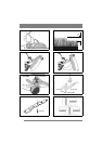
2. Remove the belt cover (5:E). The number in the
figure indicates the key width.
3. Remove the belt guide (5:F).
4. Locate the belt around the machine’s belt pulley
(16:M).
5. Force the belt onto the cutting deck’s belt pul-
ley.
6. Grip the belt tensioner’s lever with your left
hand. Pull the lever and apply the tensioner to
the outside of the belt with your right hand. See
fig. 16.
7. Install the belt guide and belt cover. See fig. 5.
8. Lift up and secure the rear section of the cutting
deck.
On machines with 17” wheels:
Install the wash-
ers and the pins in the top hole. See fig. 2.
On machines with 16” wheels:
Install the wash-
ers and the pins in the middle hole. See fig. 2.