


44
ENGLISH
GB
4.10Oil draining
The screw is removed when used engine oil is to be
drained.
The screw is shown according to the table below:
4.11Auxiliary wheel (1:L)
The auxiliary wheel is intended to assist transport
of the machine and has two positions.
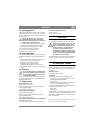
The auxiliary wheel must be folded up dur-
ing operation – Installed in the front hole.
The auxiliary wheel must be down for
transport – Installed in the rear hole.
The auxiliary wheel is folded up and down as fol-
lows:
1. Pull out the locking pin (6:T).
2. Pull out the auxiliary wheel and stay and rein-
stall in the desired position.
3. Reinstall the locking pin.
4.12Gearbox (1:M)
The gearbox becomes extremely hot
during operation. Risk of burn injuries.
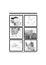
4.13Rotors (1:N)
Nobody must be close to the dangerous
rotors during operation.
The rotors are made of special steel and work the
soil at the same time as the machine is propelled
forwards. The machine can be operated with one,
two or three rotors on each side. Removal and in-
stallation of the rotors is by removing the locking
pins and screws. See fig. 8.
4.14Cutting disc (1:O).
Nobody must be close to the dangerous
cutting discs during operation.
The cutting discs are on respective rotor
axles and are designed to border the working area
and facilitate control of the machine.
4.15 Choke
The choke must never be activated dur-
ing operation. This will damage the en-
gine.
The choke must be activated at cold starts.
The choke is shown according to the table below:
4.16Fuel cock
The fuel cock should be open during operation and
closed when the machine is not used.
The fuel cock is shown according to the table be-
low:
4.17 Starting handle
Handle for starting the engine.
The starting handle is shown according to the table
below:
4.18Depth skid (1:S)
The task of the depth skid is to keep the machine
stable so that the soil can be cultivated.
The depth skid has three positions. Shifting takes
place as follows:
1. Pull out the locking pin (6:T).
2. Pull out the depth skid and reinstall in the de-
sired position.
3. Reinstall the locking pin.
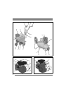
Machine Figure:Position
75-G 2:K
75R-B 1:K
75R-H 3:K
75R-HX 4:K
Machine Figure:Position
75-G 2:P
75R-B 1:P
75R-H 3:P
75R-HX 4:P
Machine Figure:Position
75-G 2:Q
75R-B 1:Q
75R-H 3:Q
75R-HX 4:Q
Machine Figure:Position
75-G 2:R
75R-B 1:R
75R-H 3:R
75R-HX 4:R