


4
MDS-JE770
PARTS No.
4-233-025-6s
4-236-047-1s
4-233-025-8s
Description
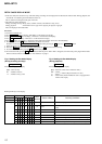
Table of Error Codes
Error Code
10
12
20
21
22
23
24
30
31
40
41
42
43
50
51
Could not load
Loading switches combined incorrectly
Timed out without reading the top of PTOC
Could read top of PTOC, but detected error
Timed out without accessing UTOC
Timed out without reading UTOC
Error in UTOC
Could not start playback
Error in sector
Retry cause generated during normal recording
Retried in DRAM overflow
Retry occurred during TOC writing
Retry aborted during S.F editing
Other than access processing, and could not read address.
Focus NG occurred and overran.
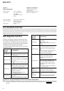
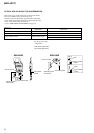
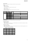
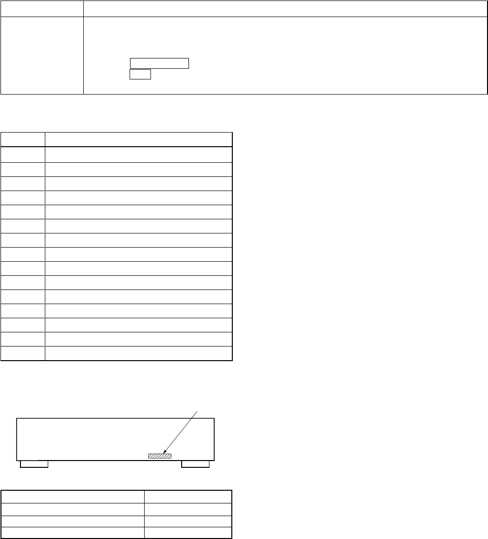
MODEL IDENTIFICATION
— BACK PANEL —
Part No.
• Abbreviation
SP : Singapore model
MODEL
AEP models
UK models
SP models
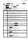
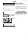
Display
History
spdl change
Mode for erasing the total spdl rp tm time
These histories are based on the time of replacement of the spindle motor. If the spindle motor has been replaced,
perform this procedure and erase the history.
Procedure
1. Press the lAMSL knob when displayed as “spdl change”
2. Press the YES button when the display changes to “spdl change?”
When “Complete!” is displayed, it means erasure has completed.
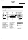
TABLE OF CONTENTS
1. SERVICING NOTES ........................................................ 5
2. GENERAL ........................................................................ 12
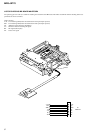
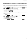
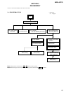
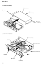
3. DISASSEMBLY
3-1. Disassembly flow .............................................................. 13
3-2. Upper Case (408226) ........................................................ 14
3-3. Front Panel Section ........................................................... 14
3-4. Main Board ....................................................................... 15
3-5. PT Board, VOL-SEL Board (SP model) ........................... 15
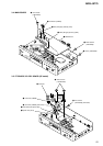
3-6. Mechanism Deck Section ( MDM-7A)............................. 16
3-7. Over Light Head (HR901), BD Board .............................. 16
3-8. Holder Assy ....................................................................... 17
3-9. Loading Motor Assy (M103) ............................................ 17
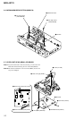
3-10. Sled Motor Assy (M102), Slider ....................................... 18
3-11. Optical Pick-up .................................................................. 18
3-12. Spindle Moter Assy (M101) .............................................. 19
4. TEST MODE ......................................................................20
5. ELECTRICAL ADJUSTMENTS ............................... 25
6. DIAGRAMS
6-1. Circuit Boards Location ..................................................... 36
6-2. Block Diagrams
•BD Section ..................................................................... 38
•Main Section .................................................................. 39
6-3. Printed Wiring Board – BD Board – ................................. 40
6-4. Schematic Diagram – BD Section (1/2) – ......................... 41
6-5. Schematic Diagram – BD Section (2/2) – ......................... 42
6-6. Schematic Diagram – Main Section (1/2) – ...................... 43
6-7. Schematic Diagram – Main Section (2/2) – ...................... 44
6-8. Printed Wiring Board – Main Section – ........................... 45
6-9. Printed Wiring Board – Display Section – ........................ 46
6-10. Schematic Diagram – Display Section –........................... 47
6-11. Printed Wiring Board – Power Section – .......................... 48
6-12.Schematic Diagram – Power Section – ............................. 49
6-13. IC Block Diagrams ............................................................ 50
6-14.IC Pin Functions ................................................................ 52
7. EXPLODED VIEWS
7-1. Chassis Section .................................................................. 60
7-2. Front Panel Section ............................................................ 61
7-3. Mechanism Section-1 (MDM-7A) .................................... 62
7-4. Mechanism Section-2 (MDM-7A) .................................... 63
8. ELECTRICAL PARTS LIST ........................................64