


33
MDS-JE770
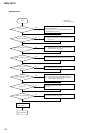
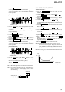
11. Rotate the l AMS L knob until the waveform of the
oscilloscope moves closer to the specified value.
In this adjustment, waveform varies at intervals of approx. 2%.
Adjust the waveform so that the specified value is satisfied as
much as possible.
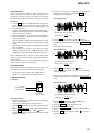
(Traverse Waveform)
12. Press the YES button, and save the adjustment results in the
non-volatile memory. (“EFB =
SAVE” will be displayed for
a moment.)
Next “EF MO ADJUS” (C07) is displayed. The disc stops ro-
tating automatically.
13. Press the A EJECT button and remove the disc.
14. Load the check disc (MD) TDYS-1.
15. Roteto l AMS L knob and display “EF CD ADJUS”
(C08).
16. Press the YES button and display “EFB = CD”. Servo is
imposed automatically.
17. Rotate the l AMS L knob so that the waveform of the
oscilloscope moves closer to the specified value.
In this adjustment, waveform varies at intervals of approx. 2%.
Adjust the waveform so that the specified value is satisfied as
much as possible.
(Traverse Waveform)
18. Press the YES button, display “EFB =
SAVE” for a mo-
ment and save the adjustment results in the non-volatile memory.
Next “EF CD ADJUS”(C08) will be displayed.
19. Press the A EJECT button and remove the check disc (MD)
TDYS-1.
Note 1 : MO reading data will be erased during if a recorded disc is
used in this adjustment.
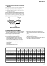
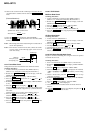
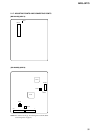
Note 2 : If the traverse waveform is not clear, connect the oscillo-
scope as shown in the following figure so that it can be
seen more clearly.
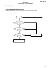
5-13. FOCUS BIAS ADJUSTMENT
Adjusting Procedure :
1. Load a test disk (MDW-74/GA-1).
2. Rotate the l AMS L knob and display “CPLAY1
MODE”(C34).
3. Press the YES button and display “CPLAY1 MID”.
4. Press the MENU/NO button when “C = AD = ” is
displayed.
5. Rotate the l AMS L knob and display “FBIAS
ADJUS”(C09).
6. Press the YES button and display “ / a = ”.
The first four digits indicate the C error rate, the two digits after
[/] indicate ADER, and the 2 digits after [a =] indicate the focus
bias value.
7. Rotate the l AMS L knob in the clockwise direction and
find the focus bias value at which the C error rate becomes 220
(Refer to Note 2).
8. Press the YES button and display “ / b = ”.
9. Rotate the l AMS L knob in the counterclockwise di-
rection and find the focus bias value at which the C error rate
becomes 220.
10. Press the YES button and display “ / c = ”.
11. Check that the C error rate is below 20 and ADER is 00. Then
press the YES button.
12. If the “( ” in “ - - ( ” is above 20, press the YES
button.
If below 20, press the MENU/NO button and repeat the
adjustment from step 2.
13. Press the A EJECT button to remove the test disc.
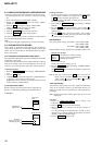
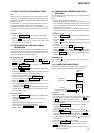
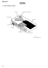
Note 1 : The relation between the C error and focus bias is as
shown in the following figure. Find points a and b in the
following figure using the above adjustment. The focal
point position C is automatically calculated from points a
and b.
Note 2 : As the C error rate changes, perform the adjustment using
the average vale.
VC
A
B
Specification A = B
VC
A
B
Specification A = B
330 kΩ
Oscilloscop
e
10pF
BD board
CN105 pin 4 (TE)
CN105 pin 6 (VC)
C error
220
b
c a Focus bias valu
e
(F. BIAS)