


16
SERVO MOTOR DRIVE
GTO Control Box – Model GTOCP2
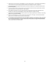
The GTO control box contains all of the circuitry to drive the two servo motors and the logic required to navigate the sky. It
will be operational and track at the sidereal rate when connected to both motors of the mount and a power source. In order
to control the movement of the mount, you will need to connect at least one of these:
• GTO Keypad controller
• Computer with astronomical software such as DigitalSky Voice (included) or Software Bisque’sTheSky™ (purchased
separately).
The GTO Servo Control Box is mounted directly onto the polar axes of the 1200 mount. Please remember that this box
contains advanced electronics and must be treated with the same care given to other fine equipment. You can see that the
unit is built to be rugged, however it is not indestructible.
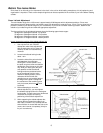
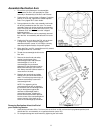
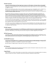
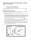
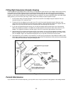
R.A. and Dec. Cable Connections
A “Y” cable with 10-pin connectors is included with your mount. Attach the connector from which the two cables emerge to
the GTO Control Panel. Attach the short part of the “Y” cable to the R.A. motor housing and the long part of the cable to the
Dec motor housing. Lock all connectors. Refer to the section below for further information about positioning the cables.
12V Connector
Place the DC power cord (included with your mount) into the phono plug outlet marked 12V on the GTO Control Panel and
lock in place. Plug the cigarette lighter plug end of the cord into your power source. The acceptable voltage range is 11.5 to
16. Suggested power sources include: portable rechargeable battery pack, auto or marine battery, or power supply (filtered
and regulated) for 110 volts with a minimum output of 5 amps at 12V DC.
There is no on-off switch. We recommend that you plug the power cable into the servo box after the keypad controller. To
turn the unit off, simply disconnect the power cable.
Considerations for observatory installations: We suggest that you disconnect your GTO Control Box from 110V when
you are not using your mount so that if your observatory experiences a power surge or lightening strike, your mount
electronics will not be damaged. If you operate your mount remotely, you will have to leave your power cable connected
just as you do for the rest of your electronic equipment. You may want to consider surge protectors or other protective
measures to protect from voltage spikes.
POWER Indicator Light
This LED will remain illuminated when your power source has sufficient output to drive the motors. If the voltage falls below
11 volts, the power light will go out and the motors will stop. The keypad controller will not function properly.
For mounts shipped after 02-25-00: If the LED turns yellow, this means that your motors are overloaded, probably due to an
unbalanced load on your mount. Refer to the troubleshooting section of the manual for the solution.
KEYPAD Connector
Attach the 5-pin male connector of the keypad controller and lock in place (push in the knurled ring then turn).