


17
Section 4 - ADJUSTMENTS & REPAIR
WARNING
DO NOT attempt any adjustments, maintenance or
service with the engine or blade running. STOP
blade. STOP engine. Set brake. Remove key. Remove
spark plug wire from spark plug and secure wire
away from spark plug. Engine and components can
be extremely hot. Avoid burns by allowing engine
and components sufficient time to cool.
4.2.4. BELT REPLACEMENT
(Continued From Previous Page)
4. Route belt onto spindle pulley. Make sure belt is
inside spindle pulley belt guide.
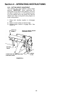
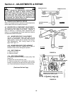
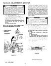
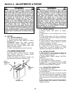
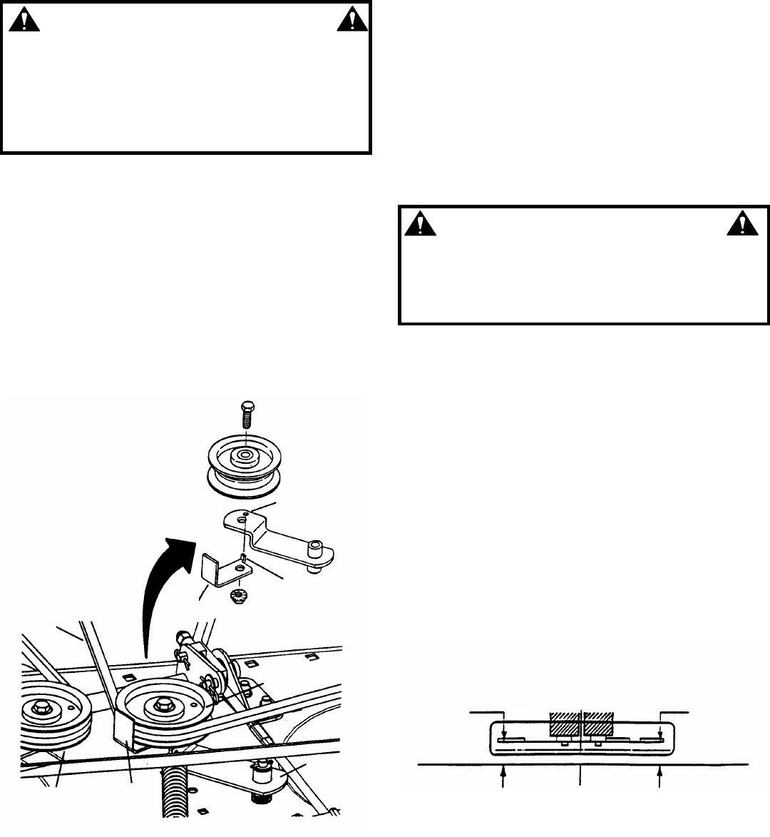
5. Reinstall idler pulley spring. See Figure 4.3.
NOTE: The idler belt guide should be positioned so
the locator tab fits into the corresponding hole found
on the idler arm. See Figure 4.3. Tighten bolt
securely.
6. Reinstall front frame cover.
NOTE: FOR ALL BELT REPLACEMENT PARTS
IDENTIFICATION NUMBERS SEE PAGE 24.
FIGURE 4.3
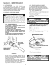
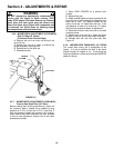
4.2.5. BLADE BRAKE
The blade switch engages the electric clutch when
pulled out to the “ON” position. When the blade
switch is in the “ON” position the cutting blade(s)
are engaged. The blade switch disengages the
electric clutch when the blade switch is pushed in to
the “OFF” position. When the blade switch is in the
“OFF” position the cutting blade(s) are disengaged.
The electric clutch is non-adjustable. The blade(s)
should stop rotation in 5 seconds or less. If the
electric clutch fails to stop the blade(s) rotation in 5
seconds, contact an authorized SNAPPER dealer to
repair or replace.
WARNING
Blades must stop rotating in 5 seconds or less after
blades have been turned off. DO NOT operate
machine until blade brake has been repaired and
functioning properly. Contact your SNAPPER dealer
for assistance.
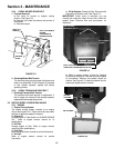
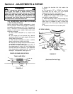
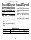
4.2.6. MOWER DECK ADJUSTMENT (LEVELNESS)
Side-To-Side (48” Decks)
Before making deck leveling adjustments, check
the tire pressure. Add or release air as needed to
bring pressure to 12 P.S.I. in front and 12 P.S.I. in
rear tires. If tires are properly inflated and mowing is
still uneven, adjust side-to-side deck levelness first
as follows:
1. Place YARD CRUISER on a smooth level
surface.
2. Remove floor pan.
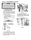
3. Rotate outside blades so tips are pointed to
the sides of deck. See Figure 4.4. Measure the
distance from blade tips to floor. If the
measurement is within 1/8” from side-to-side, the
deck levelness is satisfactory. If the difference
from side-to-side is greater than 1/8”, continue to
Step 4 for adjustment.
FIGURE 4.4
(Continued On Next Page)
IDLER ARM AND BELT
GUIDE DETAIL
42” DECK SHOWN
TAB MUST GO
INTO HOLE
LOCATOR TAB
BELT GUIDE
MOWER
BELT
IDLER PULLEY
IDLER
ARM
BELT
GUIDE
STATIONARY
PULLEY
SIDE SIDE
X
X-1/8”