


6
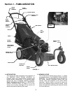
Section 2 - OPERATING INSTRUCTIONS
2.1 PRE-START CHECK LIST
Make the following checks and perform the service
required before each start-up.
2.1.1. Check guards, deflectors, grass bag, adapter
and covers to make sure all are in place and securely
tightened.
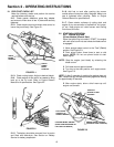
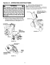
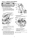
2.1.2. Check blade control and wheel drive control to
insure they work freely. See Figure 2.1.
FIGURE 2.1
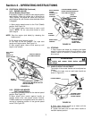
2.1.3. Check cutting height. Adjust to desired height.
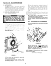
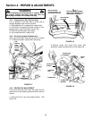
2.1.4. Check engine oil and add oil as needed to bring
level up to the full mark. Refer to Engine Owner’s
Manual for oil specifications. See Figure 2.2.
FIGURE 2.2
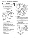
2.1.5. The battery should be removed from its carton
and filled with electrolyte. See Section on Battery
Service for battery preparation.
2.1.6. Add fuel to tank after pushing the mower
outside where fumes can safely dissipate. Make sure
cap is tightened after refueling. Refer to Engine
Owners Manual for specifications.
2.1.7. Clean exterior surfaces of cutting deck and
engine of any accumulation of spilled fuel, dirt, grass,
oil, etc. Keep engine air intake screen and cooling
fins clear at all times.
2.2 STARTING & OPERATION
2.2.1. ENGINE & BLADE
(Primer Models) (Electric Start)
When the ignition key is turned to “START”, the engine
will crank over but will not start unless the blade control
is engaged!
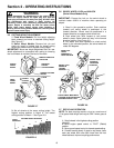
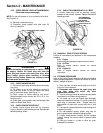
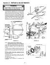
1. Move engine speed control to the “Fast” (Rabbit)
position. See Figure 2.3.
2. Push primer button three times to start a cold
engine. NOTE: Do not use primer button to start
warm engine.
NOTE: Stop the engine (and blade) by releasing the
blade control.
3. Pull blade control against handle.
4. Turn key to the start position until engine starts.
See Figure 2.3.
NOTE: If after 5 seconds of cranking the engine does not
start, release the key and attempt starting again after waiting
for approximately 20 seconds.
5. After engine starts, allow a brief warm-up until
engine runs smooth.
FIGURE 2.3
TURN KEY
SWITCH TO RUN
POSITION
ENGINE SPEED CONTROL
(SHOWN IN FAST POSITION)
PULL BLADE
CONTROL UP
AGAINST HANDLE
CATCHER MODEL SHOWN
(ROPE START MOUNTED ON
LEFT SIDE OF HANDLE)
CHECK
BLADE
CONTROL
CHECK
WHEEL
DRIVE
CONTROL