


16
Section 4 - REPAIR & ADJUSTMENTS
WARNING
Before attempting any adjustments or repairs, STOP
the engine, remove the spark plug wire from the
spark plug and secure wire away from plug.
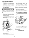
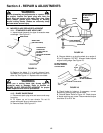
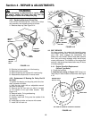
4.3.5. Replacing Bearing In Driven Disc
If the driven disc bearing fails, remove the driven
disc assembly and replace bearing as follows:
1. Remove snap ring. See Figure 4.14.
FIGURE 4.14
2. Slide the hub assembly out of the bearing.
3. Remove the four screws.
4. Remove bearing and replace with new bearing.
5. Reassemble components in reverse order.
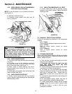
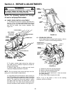
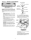
4.3.6. Replacement Of Bearing On Pulley End Of
Hex Shaft
To replace the bearing on the pulley end of the hex
shaft, proceed as follows:
1. Hold the hex shaft with an adjustable wrench
held next to the pulley.
2. Remove the 3/8” hex lock nut, which is located
on the outside of the right wheel bracket. See
Figure 4.15.
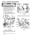
3. Remove holder, O-ring and bearing.
4. Install new bearing.
5. Carefully install new O-ring over the outside of the
new bearing.
6. Install bearing holder and secure with screws.
7. Install 3/8” hex lock nut.
FIGURE 4.15
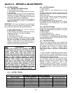
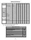
4.4. BELT SERVICE
On these mowers, the engine belt transmits power
from engine to drive disc. The drive disc powers the
poly-v belt, which engages the transmission that
powers the rear wheels. Should these belts become
worn, they could cause slippage, which would impair
mower performance. The condition of the engine belt
and poly-v belt should be checked after every 25 hours
of mower operation.
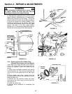
4.4.1. Engine Drive Belt Replacement
(Stretch Type Belts)
1. Empty the fuel tank.
2. Note the belt routing in Figure 4.16. There is no
idler pulley on these models to disconnect. See Figure
4.16.
TOP VIEW OF STRETCH TYPE BELT ROUTING
FIGURE 4.16
BALL BEARING
“O” RING
3/8”
HEX LOCK
NUT
BALL BEARING
HOLDER
TIGHTEN
THE FOUR
SCREWS
SNAP
RINGS
REINSTALL
DRIVEN
DISC
INSTALL
NEW
BEARING
DRIVE DISC
DRIVE BELT
ENGINE DRIVE
PULLEY