


15
Section 4 - REPAIR & ADJUSTMENTS
WARNING
Before attempting any adjustments or repairs, STOP
the engine, remove the spark plug wire from the
spark plug and secure wire away from plug.
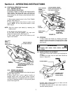
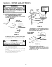
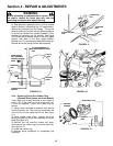
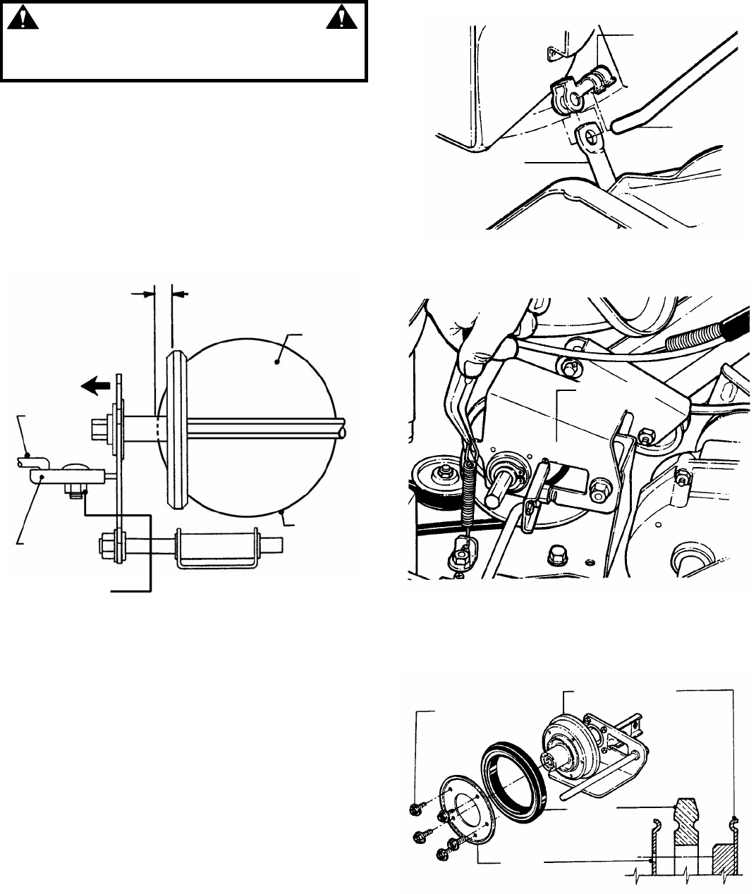
3. Slide driven disc assembly over to 1/8” from outside
edge of drive disc. Maintaining the 1/8” measurement,
remove any looseness from the linkage. This can be
done by holding the transfer rod and applying pressure
to the left (as viewed from operators position). Then
retighten the connector hex nut securely. See Figure
4.10. Move ground speed control to the first speed
position, then back to the sixth speed position.
Recheck the 1/8” measurement described previously.
Reinstall driven disc spring to driven disc assembly.
FIGURE 4.10
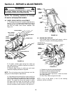
4.3.4. Replacing Driven Disc Rubber Ring
(Alternate Drive System on Some Models)
If the rubber ring is badly chunked or worn down to
within 1/16” of the metal rim of the driven disc hub,
it must be replaced. Install new rubber ring as
follows:
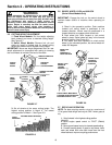
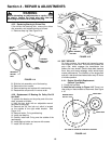
1. Using a small flat blade screwdriver, free the clip
from the transfer rod. Then remove the transfer rod
from the clip and the speed control rod. See Figure
4.11.
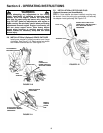
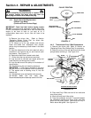
2. Using needle nose pliers, unhook the drive
spring and slide the driven disc assembly off the hex
shaft. See Figure 4.12.
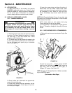
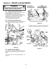
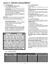
3. Remove the five machine screws and plate,
which secure the rubber ring to the driven disc hub.
See Figure 4.13.
4. Install new rubber ring.
5. Reverse above procedures for reassembly and
installation.
FIGURE 4.11
FIGURE 4.12
FIGURE 4.13
SPEED CONTROL
ROD
CONNECTOR
CLIP
TRANSFER
ROD
DRIVE DISC
ASSEMBLY
MACHINE
SCREWS
DRIVEN DISC HUB
RUBBER
RING
PLATE
1/8” MEASUREMENT TO
OUTSIDE EDGE OF DRIVE
DISC
DRIVE
DISC
SLIDE DRIVEN
DISC ASSEMBLY
TOWARD OUTSIDE
EDGE
TRANSFER
ROD
CONNECTOR
CONNECTOR
HEX NUT
OUTSIDE
EDGE