


3
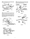
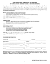
STEP 8: Check the clearance between the clutch cable
and clutch spring. NOTE: Clearance between spring and
cable is very important. Excessive clearance will cause
drive system not to operate when wheel drive control
handle is depressed. No clearance at all will cause mower
to continue to propell itself when wheel drive control handle
is released to stop the mowers forward movement. Slide
vinyl spring cover (located at the end of clutch cable) up
clutch cable to gain access to the end of spring and cable
loop. With wheel drive control handle released, clearance
between spring hook and cable loop should be 1/16” to
1/8”. If clearance is more or less than specified, unhook
spring from clutch cable eye, then adjust by turning inner
spring in an opposite direction than the outer spring.
Rehook spring to clutch cable eye. Slide vinyl cover over
the spring when correct clearance is reached. See Figure
10.
FIGURE 10
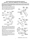
STEP 9: Driven disc to drive disc adjustment is set up
at the factory. In case driven disc may need adjustment,
proceed as follows:
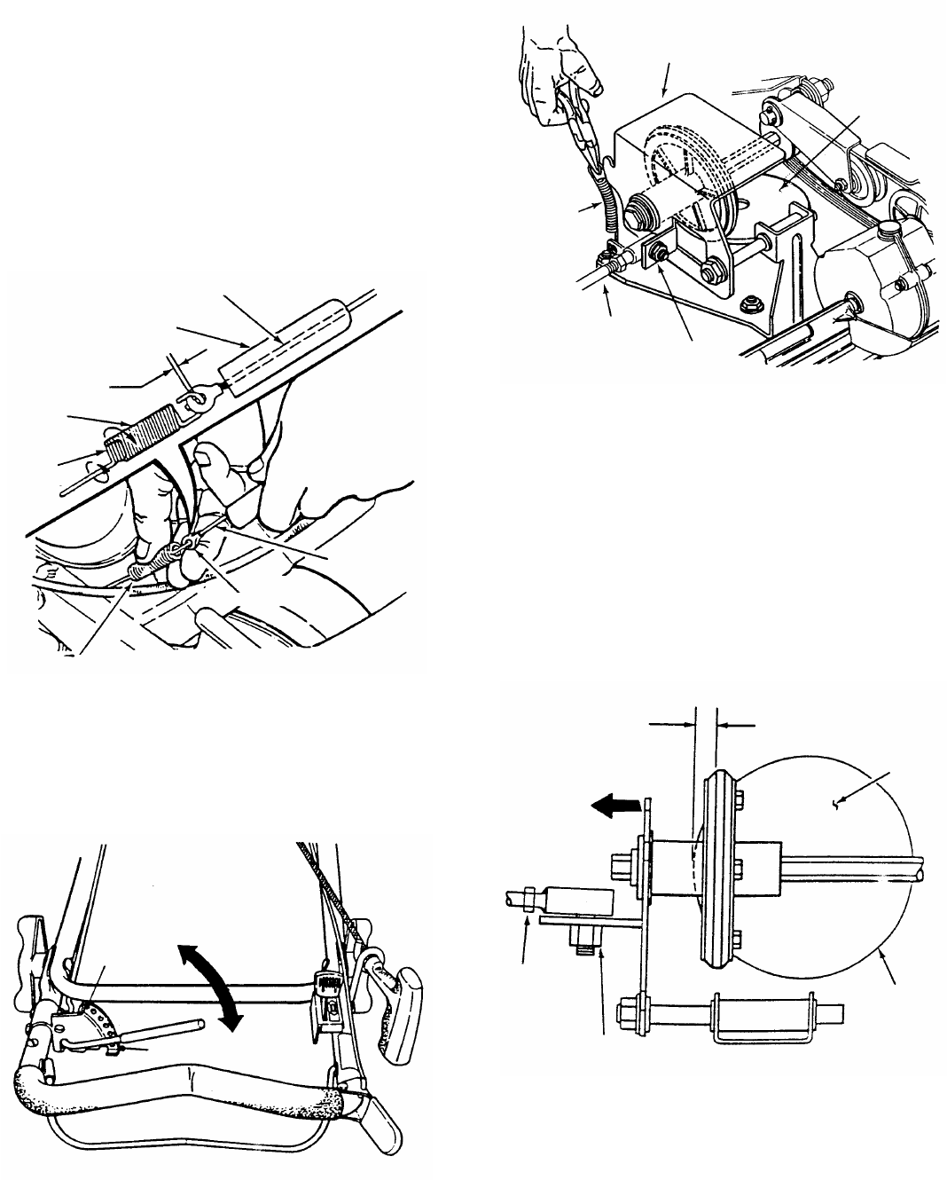
A. Place speed control rod in the number six speed
position. See Figure 11.
FIGURE 11
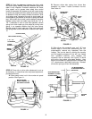
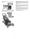
B. Remove driven disc spring from driven disc
assembly as shown. Loosen connector hex-nut.
See Figure 12.
FIGURE 12
C. Slide driven disc assembly over until 1/8” from
outside edge of drive disc. Maintaining the 1/8”
measurement, remove any looseness from the
linkage. This can be done by holding the transfer
rod and applying pressure to the left, (as viewed
from operators position), then retighten the
connector hex-nut securely. See Figure 13. Move
shift rod to the number one speed position, then
back to the number six speed position. Recheck the
1/8” measurement described previously. Reinstall
driven disc spring to driven disc assembly.
FIGURE 13
CLUTCH CABLE
VINYL SPRING COVER
1/16” - 1/8”
CLEARANCE
OUTER
SPRING
INNER
SPRING
CABLE
CLUTCH
CABLE EYE
SPRINGS
DRIVEN DISC
ASSEMBLY
DRIVEN
DISC
SPRING
TRANSFER
ROD
CONNECTOR
HEX NUT
DRIVE
DISC
1/8” MEASUREMENT
TO OUTSIDE EDGE OF
DRIVE DISC
DRIVE
DISC
SLIDE DRIVEN DISC
ASSEMBLY TOWARD
OUTSIDE EDGE
TRANSFER
ROD
OUTSIDE
EDGE
CONNECTOR HEX NUT
MOVE GROUND
SPEED CONTROL TO
SIX SPEED POSITION
SIX SPEED POSITION
SIX
ONE SPEED
POSITION
ONE