


10
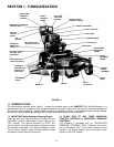
SECTION 3 - OPERATING INSTRUCTIONS
3.5 MOWER OPERATION (Continued from
Previous Page)
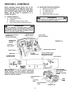
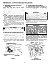
4. Move Engine Speed Control to the FAST (Rabbit)
position. Refer to Figure 3.4.
5. While holding both Traction Controls in the neutral
position, release Neutral Latch Lever by pulling
controls slightly backwards.
6. Simultaneously (and slowly), release both Traction
Controls. Machine will begin to move forward.
7. Adjust Speed Control Lever to a comfortable travel
speed.
8. Proceed to go forward while allowing machine to
travel in a straight line. If the machine has a tendency
to veer towards the LEFT or RIGHT, it can be brought
back to a straight path by moving Speed Control
Lever in the desired direction of travel. Refer to Figure
3.5.
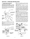
9. Squeeze the appropriate Traction Control to turn the
machine either LEFT or RIGHT.
10. If either Traction Control is squeezed tightly against
the handlebar, it will cause the corresponding wheel
to reverse direction and “zero-turn” the machine. BE
CAREFUL!
WARNING
DO NOT use Rider Attachment (Sulky) on slopes! DO
NOT park machine on slopes.
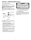
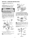
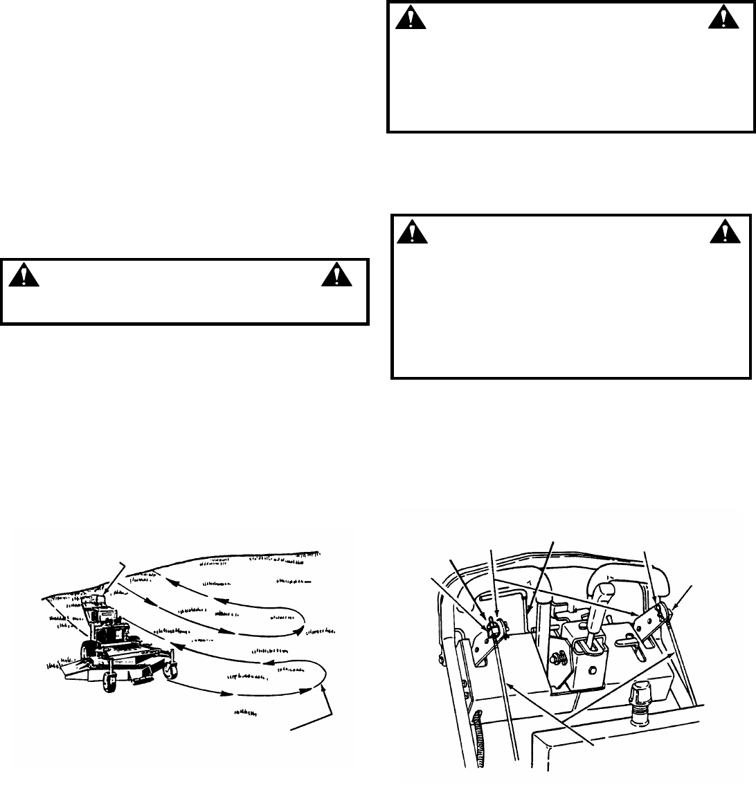
3.6 MOWING AND TURNING ON HILLSIDES
1. Always mow hillsides starting at bottom of hill. Mow
across slopes, never up and down. Exercise
CAUTION when changing directions on slopes. DO
NOT MOW STEEP SLOPES. See Figure 3.7.
2. Hillside mowing is accomplished by squeezing
Traction Lever on the UPHILL SIDE of machine. This
helps prevent side slipping of mower.
3. When turning mower on hillsides, always turn toward
the UPHILL SIDE of mower for better control and
balance.
FIGURE 3.7
3.7 HANDLE HEIGHT ADJUSTMENT
For operator comfort the height of the handlebars are
adjustable to five different positions. The handle height
adjustment procedure is sensitive and the following
procedures and WARNINGS must be followed very
carefully.
WARNING
Several steps of the handle bar height adjustment
procedure require that the engine be started.
Exercise extreme CAUTION when making
adjustments while the engine is running to avoid
HOT engine components, rotating components, run
over or entrapment types of injuries.
IMPORTANT: To complete this procedure, a steel rod
5/16” diameter and 7-3/4” long will be required. DO NOT
begin this procedure without it.
WARNING
Before attempting any adjustments, maintenance,
service, or repairs, stop engine and blade, close fuel
shut-off valve, and allow engine to cool. Always turn
Ignition Key to STOP, remove key from ignition
switch, disconnect spark plug wire(s) and secure
wire(s) away from spark plug(s). If machine is to be
raised or tilted. Make sure to secure machine in
place to prevent it from falling.
STEP 1: Move machine to smooth level place. Raise
rear of machine just high enough for drive wheels to
clear the floor and be able to rotate freely. Block machine
securely to prevent it from falling.
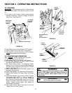
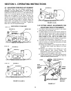
STEP 2: Place traction control levers in the Neutral
position and engage Neutral Latch. See Figure 3.8.
FIGURE 3.8
(Continued on Next Page)
SQUEEZE TRACTION CONTROL
LEVER ON UP-HILL SIDE OF
MOWER
ALWAYS TURN
MOWER TOWARD
HILL
* ALWAYS START AT BOTTOM OF HILL!
* ALWAYS MOW ACROSS HILL - NEVER
UP & DOWN.
SWIVEL
JAM NUT
TRACTION
CONTROL
ARMS
NEUTRAL
LATCH
SELF LOCK
COTTER PIN
SWIVEL
TRACTION CONTROL
RODS