


23
Section 3 - OPERATING INSTRUCTIONSSection 5 - ADJUSTMENTS & REPAIR
5.3 TRACTION BELT TENSION
The traction drive belt tension does not require adjustment.
If the belt is slipping, it will have to be replaced.
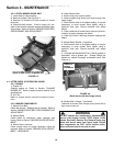
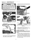
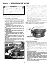
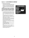
5.4 TRACTION BELT REPLACEMENT
1. Remove mower drive belt from around clutch pul-
ley. See Figure 5.10. Refer to Section "MOWER
DRIVE BELT REPLACEMENT AND ADJUSTMENT".
2. Turn lock nut out to the end of eyebolt, reducing
spring tension. Unhook traction idler spring from bolt in
frame. See Figure 5.10.
3. Remove anti-rotation bracket. See Figure 5.10.
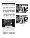
4. Disconnect the electric clutch from main wire har-
ness.
5. Remove traction belt from around engine pulley
and hydro pumps.
6. Install new belt and route around engine pulley and
hydro pump pulleys.
7. Reconnect electric clutch to main wire harness.
8. Reinstall anti-rotation bracket and tighten nuts
securely.
9. Reattach traction idler spring. Run lock nut all the
way to the end of the threads on the eyebolt. See
Figure 5.10.
10. Reinstall mower drive belt onto clutch pulley.
Refer to Section "MOWER DRIVE BELT REPLACE-
MENT AND ADJUSTMENT".
EYEBOLT
FIGURE 5.10
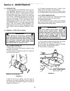
WARNING
DO NOT attempt any maintenance, adjustments or
service with engine running. STOP engine. STOP
blades. Set brake. Remove key. Remove spark plug
wires and secure away from spark plugs. Engine and
components are HOT. Avoid serious burns; allow suf-
ficient time for all parts to cool.
!
!
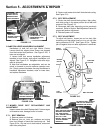
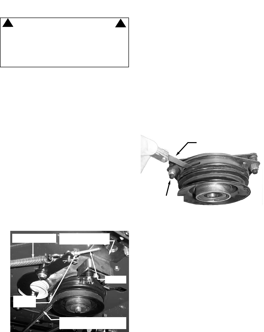
FIGURE 5.11
UNHOOK TRACTION
DRIVE IDLER SPRING
LOOSEN
LOCK NUT
REMOVE ANTI-ROTATION
BRACKET
REMOVE MOWER DRIVE BELT
FROM AROUND CLUTCH PULLEY
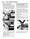
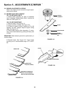
INSERT FEELER GAUGE.
GAP SHOULD BE .015
ROTATE NUTS IN OR
OUT TO ACHIEVE
CORRECT GAP
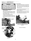
5.5 BLADE BRAKE/ELECTRIC CLUTCH ADJUSTMENT
The blade switch engages the electric clutch when
pulled out to the "ON" position. When the blade switch
is in the "ON" position the cutting blade(s) are
engaged. The blade switch disengages the electric
clutch when the blade switch is pushed in to the "OFF"
position. When the blade switch is in the "OFF" posi-
tion the cutting blade(s) are disengaged. The electric
clutch is adjustable. The blades should stop rotation in
5 seconds or less. If the electric clutch fails to stop the
blades rotation in 5 seconds, adjustment is necessary.
1. Insert a feeler gauge into the three slots on the
electric clutch.
2. Check gap through all three slots in the side of the
clutch. The gap should be set at .015.
3. If gap is incorrect rotate nuts in or out to achieve the
correct gap. See Figure 5.11.
NOTE: Electric Clutch is shown removed from the
machine. Removal is not necessary for adjustment.
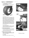
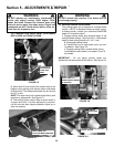
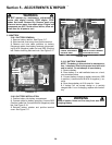
5.6 TRACKING ADJUSTMENT
If the machine does not track straight when the Motion
Control Levers are in the maximum forward speed
position, perform the following adjustment. Rear tire
pressure must be set to 12 PSI before making this
adjustment.
1. Loosen bolts that secure adjustment plates and
slide plates all the way forward. Retighten bolts. See
Figure 5.12.
2. Start machine and drive in smooth flat open area at
maximum forward speed.
3. If machine tracks to the right, loosen bolts that
secure the left adjustment plate. Move plate rearward
to slow the left wheel. Retighten bolts.
4. If machine tracks to the left, loosen bolts that
secure the right adjustment plate. Move plate rearward
to slow the right wheel down. Retighten bolts. See
Figure 5.12.
5. Drive machine again. Repeat adjustment as neces-
sary until machine tracks straight.