


10
Section 3 - OPERATING INSTRUCTIONS
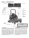
3.1 PRE-START CHECK LIST
Make the following checks and perform the service
required before each start-up.
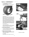
3.1.1. Check tires and add or release air as needed to
bring pressure to 12 psi in drive tires. Pressure in front
caster wheels should be 25 psi.
3.1.2. Check guards, deflectors and covers to make
sure all are in place and securely tightened.
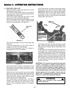
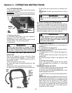
3.1.3. Check engine oil and add oil as needed to bring
level up to the FULL mark. Refer to engine owner's
manual for oil specifications. See Figure 3.1.
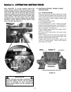
3.1.4. Check blade switch to insure it works freely. See
Figure 3.2.
1. Pull the blade switch up to the "ON" position to
engage or turn "ON" the mower blades.
2. Push blade switch down to the "OFF" position to
disengage (or turn "OFF") the blades.
3.1.5. Clean exterior surfaces of cutting deck, engine
and pumps of any accumulation of dirt, grass, oil, etc.
Keep engine and pump air intake screens and cooling
fins clear at all times.
3.1.6. Add fuel to both tanks of the machine outside
where fumes can safely dissipate. Make sure both fuel
filler caps are tight. Note the fuel tank selector valve
behind left side of operator's seat. Refer to engine
owner's manual for fuel specifications.
3.1.7. Adjust position of operator's seat. The seat is
mounted to its base with two knobs and two bolts.
Loosen knobs and bolts, slide seat forward or back-
ward for most comfortable position, and retighten
hardware.
Section 3 - OPERATING INSTRUCTIONS
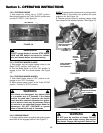
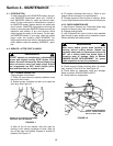
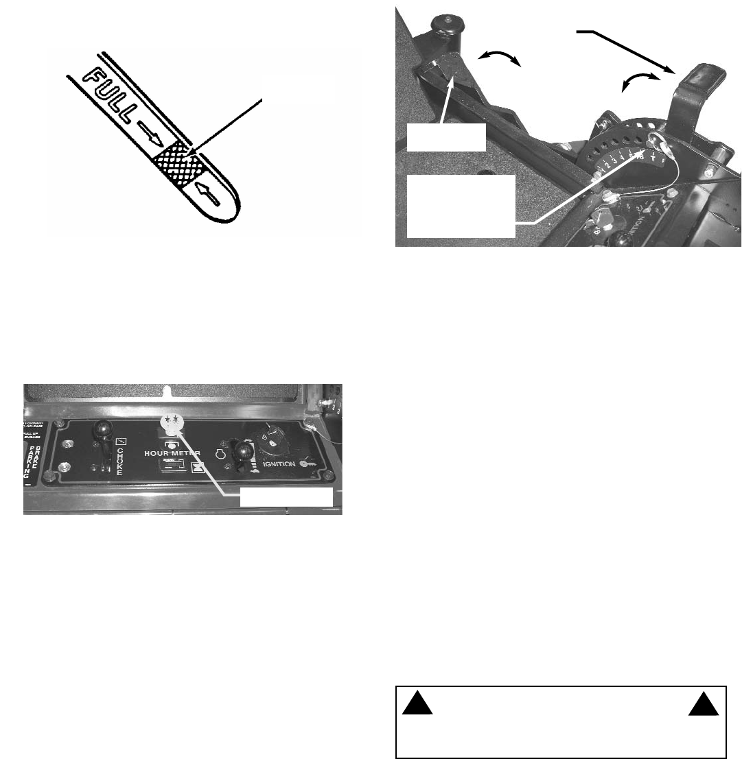
3.1.8. Place mower in desired cutting height setting.
Grasp deck lift lever and move lever to desired cutting
height setting. Insert stop pin to desired cutting height.
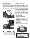
IMPORTANT: There is a foot assist pedal located to
the right front side of the footrest. Always use this
assist pedal to raise or lower the deck to the desired
cutting height. See Figure 3.3.
3.1.9. Check seat belts. Mounting hardware must be
tight. Buckle must latch securely and release easily.
Webbing must not display signs of deterioration, wear
or damage.
3.1.10. Check roll bar protective structure for structur-
al soundness (i.e. no cracks, damage, corrosion, etc.)
All hardware must be tight. Roll bar must be raised and
locked unless absolutely necessary (i.e. low overhead
clearance). Both locking pins must be installed and
securely fastened to prevent inadvertent removal. DO
NOT operate a machine that has had any part of the
roll bar protective structure removed, damaged, or
modified in any way.
IMPORTANT: This machine is equipped with hydrostat-
ic drive. The direction of motion and the speed of
motion are controlled by the left and right motion con-
trol levers. A small movement of these controls can
cause the machine to move instantly. DO NOT attempt
to operate the machine until you read this manual and
become familiar with its operation. Practice with the
blades "OFF" disengaged, engine speed at a slow set-
ting and in an open area away from obstacles.
SAFE LEVEL
AREA
FIGURE 3.1
FIGURE 3.2
BLADE SWITCH
DECK LIFT
LEVER
FIGURE 3.3
WARNING
DO NOT allow operation of the machine by
untrained personnel.
!
!
FOOT ASSIST
PEDAL
INSERT STOP PIN
INTO HOLES FOR
DESIRED CUTTING
HEIGHT