


www.snapper.com24
Maintenance
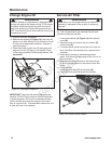
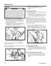
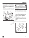
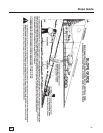
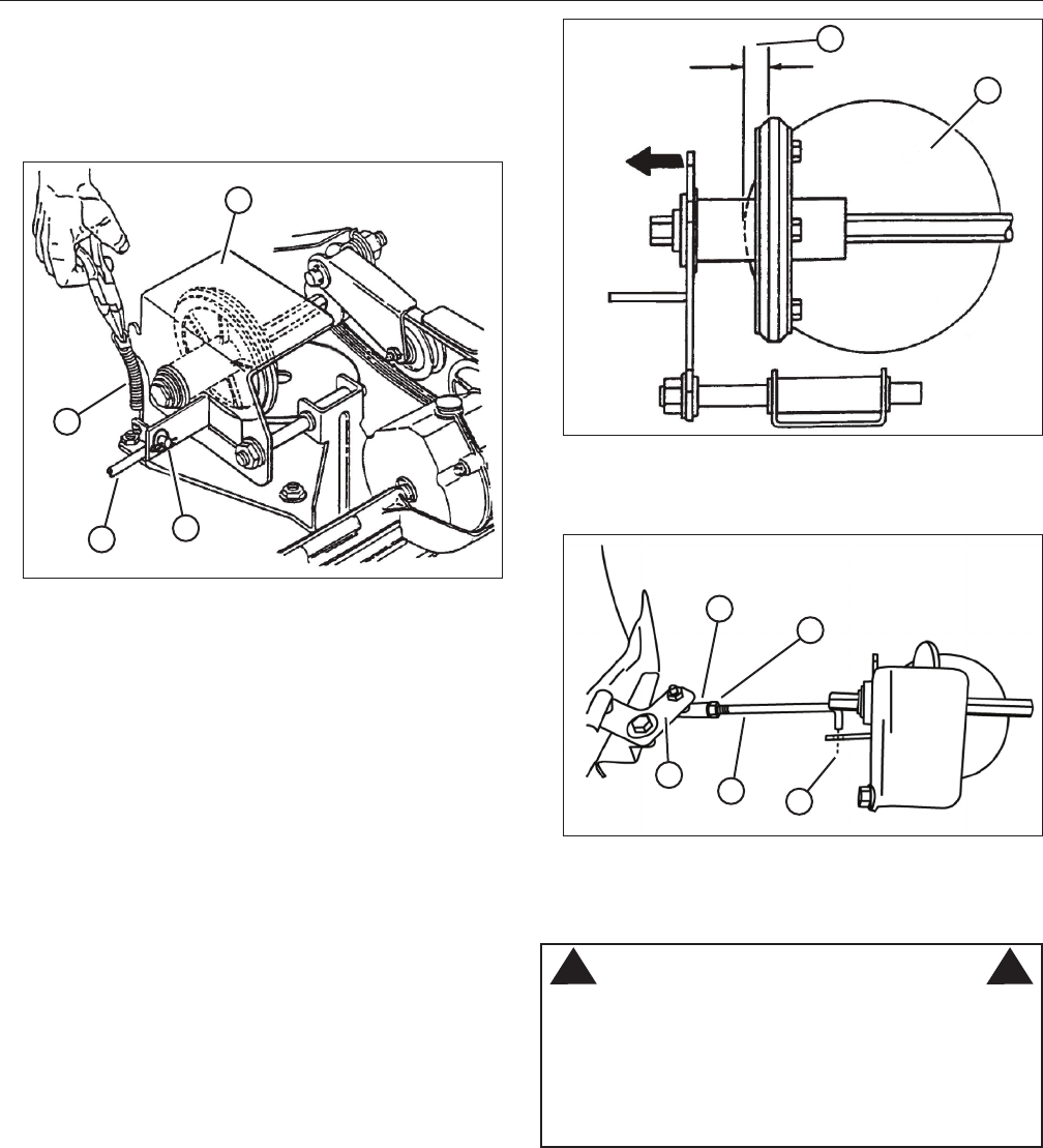
2. Remove the driven disc spring (A, Figure 26) from
the driven disc assembly (B). Also remove the
pin and washer (C) from the transfer rod (D), and
remove the end of the transfer rod from the hole in
the driven disc assembly.
D
B
C
Figure 26: Adjusting the driven disc
A
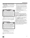
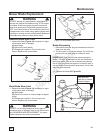
3. Slide the driven disc assembly over to 1/8” (A,
Figure 27) from the outside edge of the drive disc
(B).
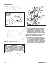
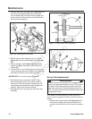
4. Loosen the jam nut (A, Figure 28) securing the
transfer rod (B) to the ball joint (C) on the pivot
bracket (D).
5. Turn the rod in or out of the ball joint until the end
of the rod aligns with the hole (E) in the driven disc
assembly from which the rod was removed.
IMPORTANT: Do not move the pivot bracket.
6. Reinstall the rod as removed in Step 2. Move
the ground speed control to the ‘slow’ position,
then back to the ‘fast’ position. Recheck the 1/8”
measurement described previously. Readjust as
needed. Tighten the nut when finished.
7. Reinstall the driven disc spring to the driven disc
assembly.
B
Figure 27: Proper driven disc adjustment
A
A
Figure 28: Adjusting the transfer rod
E
C
D
B
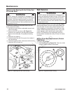
Driven Disc Replacement
WARNING
DO NOT attempt any maintenance, adjustments or
service with engine and blade running. STOP engine
and blade. Disconnect spark plug wire and secure
away from spark plug. Engine and components are
HOT. Avoid serious burns, allow sufficient time for all
components to cool.
! !
If the rubber on the driven disc is badly chunked or
worn, it must be replaced. Install a new driven disc as
follows:
1. Remove the pin and washer (C, Figure 26) from
the transfer rod (D), and remove the end of the
transfer rod from the hole in the driven disc assem-
bly.
Not for
Reproduction