


29
Regular Maintenance
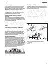
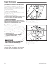
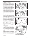
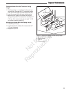
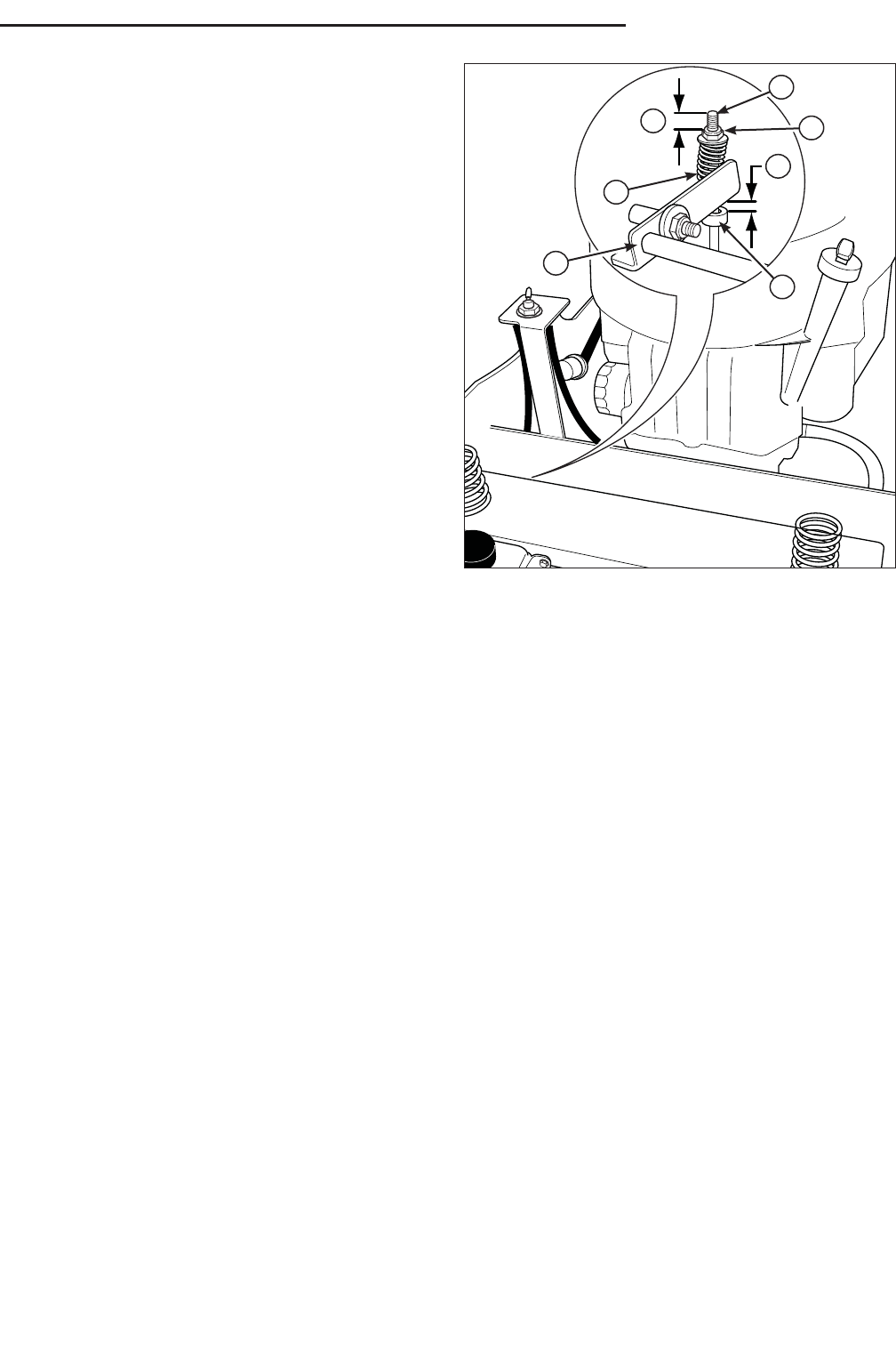
Figure 34. Parking Brake Adjustment
A. Brake Spring
B. First Measurement - .50” (1,27 cm)
C. Brake Spring Rod
D. Lock Nut
E. Second Measurement - .375” (0,95 cm)
F. Set Collar
G. Brake Shaft Weldment
A
B
E
G
C
D
F
Parking Brake Adjustment
1. Disengage the PTO, stop the engine, engage the parking
brake, and remove the key from the ignition.
2. Raise the seat plate to gain access to the parking brake
components.
3. Measure the distance from the top of the brake spring
rod (C, Figure 34) to the top of the lock nut (D) on both
sides of the unit. The measurement should be .50”
(1,27 cm). If not, adjust the locknut to achieve the
measurement of .50” (1,27 cm)
4. Measure the distance between the bottom of the brake
shaft weldment (G) and the top of the set collar (F). The
measurement should be .375” (0,95 cm). If not, position
the set collar until the measurement equals .375” (0,95
cm).
If this does not correct the braking problem, see
your dealer.
Not for
Reproduction