


25
Regular Maintenance
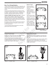
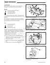
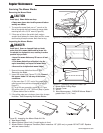
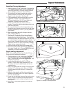
Figure 24. Checking Transmission Oil Level
A. Transmission Oil Reservoirs
B. “FULL COLD” mark
A
B
Check / Fill Transmission Oil
Oil Type: 20W-50 conventional detergent motor oil.
1. Check the oil level when the unit is cold. Locate the
transmission oil reservoirs (A, Figure 24) located on the
seat support plate. The oil should be up to the “FULL
COLD” mark (B). If the oil is below this level, proceed
to step 2.
2. Before removing the reservoir caps, make sure the area
around the reservoir cap and fill neck of the reservoir is
free of dust, dirt, or other debris. Remove the reservoir
cap.
3. Add oil up to the “FULL COLD” mark (B).
4. Reinstall the reservoir caps.
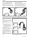
Transmission Oil Filter Change
Change Interval: Every 200 Hours
Replacement Filter Number: 5101026X1
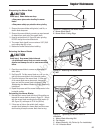
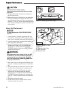
1. Locate the transmission oil filters (A, Figure
25) underneath the rear of the machine on the
transmissions.
2. Remove the three 1/4” filter guard screws (C) and the
filter guard (B).
3. Clean the area around the filter base and remove the
filter.
4. Apply a film of new oil to the gasket of the new
replacement filter. After the oil has drained, thread the
new filter onto the filter base until the gasket makes
contact, then tighten 3/4 of a turn more.
5. Reinstall the filter guard with the three 1/4” filter guard
screws
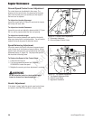
6. Using a hex bit swivel socket or a modified allen wrench
remove the top port plug from the transmissions.
7. Remove the transmission reservoir cap and fill with oil
until oil appears at the bottom of the transmission’s top
port (approximately 2 qts (1,89L).
8. Reinstall the top port plug and tighten to 15 ft lbs (20,38
Nm).
9. Continue to add oil to the transmission oil reservoirs
until the oil level reaches the “FULL COLD” mark.
Reinstall the oil reservoir cap.
10. Repeat this process for the other side of the machine.
11. Run the unit for several minutes and check the
transmission oil level.
IMPORTANT NOTE: Use caution after changing
the filter; air in the hydraulic system may affect the
responsiveness of the ground speed control levers.
Repeat step 11 until the air is out of the system.
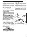
Figure 25. Transmission (Left Side Shown.)
A. Transmission Oil Filter
B. Filter Guard
C. 1/4” Filter Guard Screws
D. Top Port Plug
A
B
C
D
Not for
Reproduction