


15
Initial Setup & Assembly
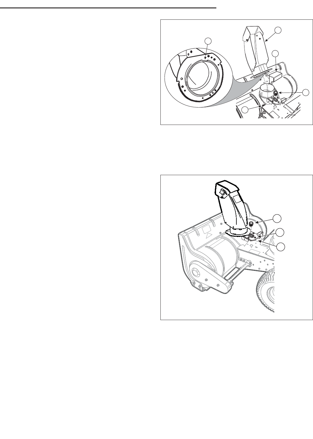
A
B
D
E
C
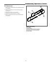
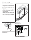
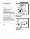
Figure 9. Chute Assembly
A. Chute Rotator Drive Cover Bolt
B. Chute Rotator Drive Cover
C. Chute Rotator Drive Assembly
D. Chute Assembly Notch
E. Chute Assembly
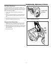
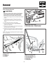
CHUTE ASSEMBLY
1. Carefully unpack and organize Snow thrower parts.
2. Remove chute rotator drive cover (B, Figure 9) from
the snow thrower assembly by removing hex screw
(A) and tilting the gearbox cover to disengage tab on
opposite side of box.
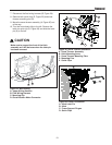
3. Remove chute rotator gear from shaft (C).
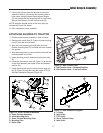
Note location of notch (D) in chute ring gear. Align
the notch in the chute assembly with the guide tab at
the base of the discharge outlet.
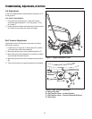
4. Slide chute (E) into place and rotate chute 180
degrees to front.
Note: Chute opening should be facing front/center of
machine.
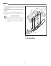
5. Replace chute rotator gear (A, Figure 10) onto shaft
and rotate to align chute ring gear and drive gear.
6. Loosen, but do not remove the 3 hex bolts (B) hold-
ing chute rotator drive assembly to the snow thrower.
7. Move chute rotator drive assembly (C) toward chute
until the chute ring gear meshes with the rotation
motor drive gear. Tighten the 3 hex bolts.
8. Replace chute gearbox cover over rotator (B, Figure
9)gear mechanism and secure with the hex bolt.
A
B
C
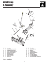
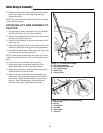
Figure 10. Chute Assembly
A. Chute Rotator Gear
B. Hex Bolts
C. Chute Rotator Drive Assembly