


4
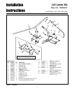
Installation Instructions Lift Lever Kit
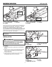
Figure 8. Install Lift lever Assembly.
A. Lift Lever Assembly C. Hair Pin
B. Clevis Pin D. Mounting Bracket
C
Install Front Attachment Lift Lever & Rod
ALL MODELS
1. Slide the lift lever assembly (A, Figure 8) on to the
end of the shaft assembly and on to the edge of the
tractor.
2. Secure to mounting bracket (D) using clevis pins (B)
and hair pin (C).
B
B
A
Edge of
Tractor
End of
Shaft
Assembly
D
B
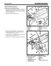
Figure 9. Install Lift Rod
A. Lift Rod C. Hair Pin
B. Lift Lever Assembly
A
C
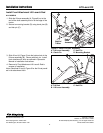
3. Slide lift rod (A, Figure 9) into the bottom hole in the
lift lever assembly (B). Secure with hair pin. Install
front attachment & hitch as outlined in Operator’s
Manual or Installation Instructions.
4. Removal of Front Attachment Lift Lever & Rod is
reverse of installation.
Note: Substitute lift rod A, Figure 9 for the lift rod provid-
ed in the attachment hitch.
Form No. 1731401
Revision 01 Rev. Date 11/2005
© 2005 Simplicity Manufacturing, Inc. All Rights Reserved
TP 200-4229-01-AT-SMAN
MANUFACTURING, INC.
500 N Spring Street / PO Box 997
Port Washington, WI 53074-0997 USA