


3
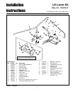
Lift Lever Kit Installation Instructions
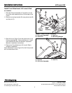
3. Mount the lift shaft assembly (A, Figure 7) to the
frame using three 5/16-18 x 1 capscrews (B) and
5/16-18 flange nuts (C) as shown.
4. Install 5/16-18 x 1-1/2 capscrew (D), spacer (F), bell
crank (G), washer & 5/16-18 nut (I).
5. Install rod (H), and hair pin & washer (E) if removed.
Figure 7. Install Lift Shaft Assembly & Rod.
A. Lift Shaft Assembly E. Hair Pin & Washer
B. Capscrews, Hex F. Spacer
5/16-18 x 1 G. Bell Crank
C. Flange Nuts, 5/16-18 H. Rod
D. Capscrew, Hex I. Washer & Nut, 5/16-18
5/16-18 x 1-1/2
B
C
A
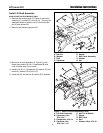
Figure 6. Rod & Bell Crank Removal
A. Hair Pin E. Spacer
B. Washer F. Bell Crank Assembly
C. Rod G. Washer
D. Capscrew H. Nut
A
A
B
C
D
E
F
H
G
B
G
F
H
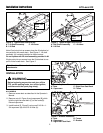
Install Lift Shaft Assembly
SINGLE POINT PICK-UP MODELS ONLY
1. Remove and retain spacer (E, Figure 6), bell crank
assembly (F), washer (G), and nut (H). You may find
installation easier to remove rod (C) and one cotter
pin (A) and washer (B).
2. Remove and discard capscrew (D).
B
C
D
I
E
E