


2
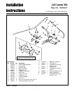
Installation Instructions Lift Lever Kit
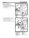
INSTALLATION
ALL MODELS
1. Remove mower deck as described in the Operator’s
Manual.
2. Remove nuts (A, Figure 4) and capscrews (B) which
hold the right rear seat deck (C) to the frame(D).
Discard capscrews.
3. Install bracket (E, Figure 5) using new 5/16-18 x 1-
3/4 capscrews (B) and 5/16-18 nuts (A).
This kit adds a lift lever for front mounted
attachments.
Before beginning any service work turn off the
PTO, set the parking brake, turn off the ignition,
and disconnect the spark plug wire(s).
WARNING
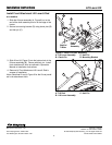
Figure 4. Capscrew Removal
A. Nuts C. Right Rear Seat Deck
B. Capscrews D. Frame
Figure 5. Bracket installation
A. Nuts D. Frame
B. Capscrews E. Bracket
C. RIght Rear Seat Deck
A
D
B
C
A
D
B
C
E
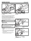
Figure 3. Typical Single Point Pick-Up
A. Bell Crank Assembly C. Lift Lever
B. Lift Rod
A
B
Note: Dual point pick-up mowers have the lift attached at
two points on the mower deck. See Figure 2. Lift shaft
assembly (A) is already installed on these tractors.
Do not replace with lift shaft assembly provided in kit.
Single point pick-up mowers have the lift attached at one
point on the mower deck. See Figure 3.
Mower Lift
Point
C
Figure 2. Typical Dual Point Pick-Up
A. Lift Shaft Assembly C. Lift Lever
B. Lift Rod
A
B
Mower Lift
Points
C