


10
Initial Assembly & Installation
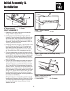
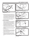
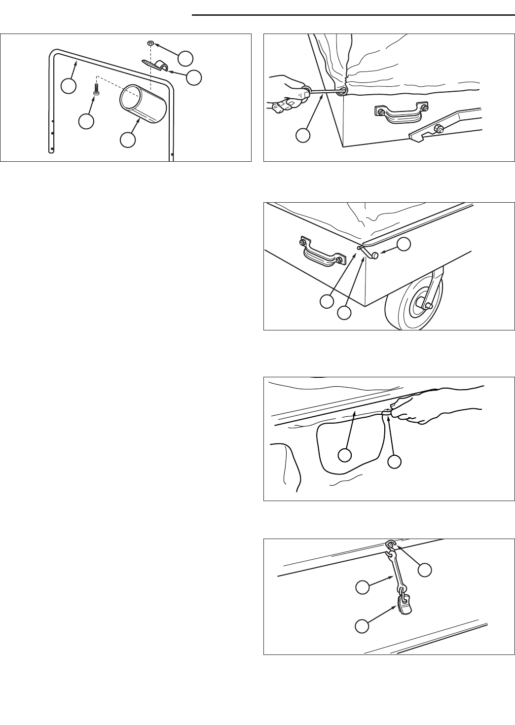
6. Install the sleeve clamp (C, Figure 15) to the connect-
ing sleeve (A) with 1/4-20 x 1/2 slotted truss head
screw (D) and nyloc nut (E). Install the connecting
sleeve inside the collar of the cover and position
sleeve clamp (C) over the support tube (B).
7. Thread the straight rod (A, Figure 16), which has an
eyelet on each end, through the sleeve at the front of
the cover.
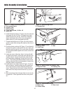
8. Pinch the black cord loop (B, Figure 17) and thread it
through the eyelet on each end of the rod. Next, pull
the loop over the top bolt (C) on each side of the box.
The rod gives added support to the cover at the front
of the box.
9. Inside the cover at the front, there is a long tab with
an eyelet on the end. Pull this tab over the top of the
support tube (A, Figure 18) and back under the sup-
port tube before threading it through the slot in the
cover. This locking tab (B) secures the cover to the
support tube when the cover assembly is locked into
the open position for dumping.
10. Install the six inch rubber strap (B, Figure 19) at the
back of the box. Hook the strap over the metal loop
(A) on the frame rod, which protrudes through the
cover. Close the hook with a pair of pliers. Hook the
other end of the strap over the door lock (C) on the
box.
11. Slide connecting sleeve through hole in cover on dis-
charge side. Cover opposite hole with cover provid-
ed.
Figure 17. Secure Cover
A. Straight Rod C. Bolt
B. Cord Loop
C
A
B
Figure 18. Secure Cover To Support Tube
A. Support Tubes B. Locking Tab
A
B
Figure 19. Install Rubber Strap
A. Metal Loop C. Door Lock
B. Rubber Strap
B
A
C
Figure 16. Install Straight Rod
A. Straight Rod
A
Figure 15. Install Connecting Sleeve
A. Connecting Sleeve
B. Support Tube
C. Sleeve Clamp
D. Truss Head Screw, 1/4-20 x 1/2
E. Nyloc Nut
B
C
E
A
D