


9
Initial Installation & Assembly
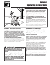
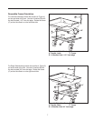
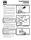
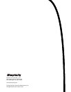
6. Install support tube (A, Figure 10) inside the box.
Align each end of the support tube with the two holes
at the front corner side of the box. Place one 5/16-18
x 1-1/2 hex bolt with a 5/16 flat washer and plastic
spacer through the top, outside hole of the box and
the support tube. Secure with a 5/16 locknut on the
inside. At the bottom hole place on 5/16-18 x 1-1/2
hex bolt with a 5/16 flat washer through the box and
the support tube. Secure with a 5/16 locknut.
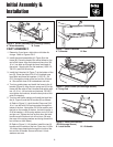
COVER ASSEMBLY
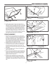
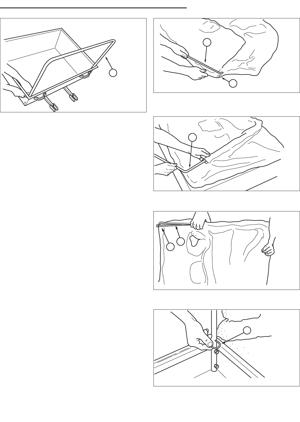
1. Unfold the cover and spread it out on a flat, clean
surface. The two 3/8 inch rods are threaded through
two sleeves inside the cover. The rod with the two
bent ends is called the frame rod (B, Figure 11),
since it lays on top of the box's frame. The rod with
the two eyebolt ends is called the support rod, since it
supports the top, rear side of the cover.
2. Thread the frame rod (B, Figure 11) through the bot-
tom sleeve of the cover so that the two bent ends
protrude through the openings on each side. The
openings (A) of the sleeve are found next to the black
cord loops.
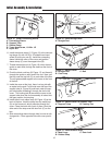
3. Thread the support rod (A, Figure 12) through the
sleeve inside the cover.
4. Pick up the cover by holding the rods and place the
support rod inside the frame rod before hooking the
frame rod (A, Figure 13) through the eyelet of the
support rod (B) on each end.
5. Place the cover assembly over the support tube.
Insert the frame rod with the support rod attached
through the hole in the support tube and secure with
a flat washer and cotter circle (A, Figure 14) on each
side.
Figure 12. Install Support Rod
A. Support Rod
A
Figure 13. Connect Frame Rod and Support Rod
A. Frame Rod B. Support Rod
A
B
Figure 14. Secure Rods
A. Safety Clip
A
Figure 10. Install Support Tube
A. Support Tube
A
Figure 11. Install Frame Rod
A. Opening B. Frame Rod
B
A