


17
Initial Setup & Assembly
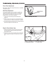
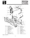
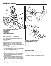
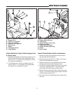
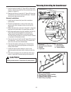
Install Chute Rotator Switch and Harness
1. Remove the plug from the switch mounting hole in
the right side of the dashboard.
2. Route the switch harness (C, F, Figure 15) through
the frame and dashboard as shown.
3. Install the switch (G) in the dashboard and connect
the upper end of the switch harness (F) to it.
4. Connect the red/yellow power lead (H) to the red/yel-
low tractor harness lead (E). Connect the black
power lead to the black tractor harness lead.
5. Mount the trailer plug socket (B) in the frame at loca-
tion (D). Connect the trailer plug lead (B) to the lower
switch harness connector (C).
6. Do not connect the snowthrower wire harness (A) at
this time.
Figure 15. Install Power Port & Switch
A. Rotator Motor Harness
B. Trailer Plug
C. Switch Harness Lower Plug
D. Plug Hole (Frame)
E. Tractor Harness Leads
F. Switch Harness Upper Plug
G. Switch
H. Power Leads
G
C
A
D
H
E
F
G
B
F
H
E
C
D
B
A
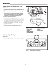
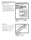
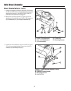
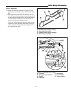
Figure 14. Deflector Control Cable Support Arm
A. Support Arm
B. 5/16-18 x 1 Capscrew
C. Lockwasher & Nut
D. 3/8-16 x 1-1/4 Capscrew
E. Assist Lever
F. Spacer
G. Lockwasher & Nut
H. Large Washer
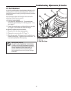
Attach Deflector Control Cable Support Arm
& Assist Lever
1. Assemble the deflector control cable support arm (A,
Figure 14) to the left side of the snowthrower using
one 5/16-18 x 1” capscrew (B), lockwasher, and nut
(C) using the holes shown.
2. If not already done, install the lift assist lever (E)
using a 3/8-16 x 1-1/4 capscrew (E), large washer
(H), spacer (F), lockwasher & nut (G).