


16
Initial Setup & Assembly
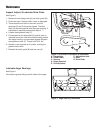
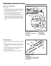
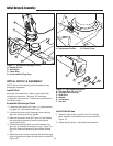
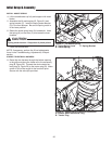
Figure 11. Assemble Discharge Chute
A. Plastite Screw
B. Hold-Down
C. Chute Ring
D. reinforcement Ring Gear
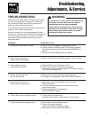
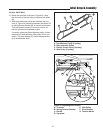
Figure 12. Discharge Chute Motor Adjustment
A. Adjustment Screws B. Plastic Cover
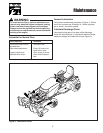
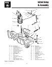
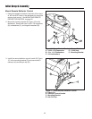
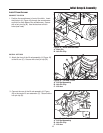
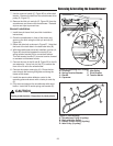
Figure 13. Skid Shoe Installation
A. Carriage Bolt, 3/8-16 x 3/4”
B. Snowthrower Housing
C. Skid Shoe
D. Washer
E. Lockwasher
F. Hex Nut
A
B
C
D
E
F
A
B
A
A
D
B
C
INITIAL SETUP & ASSEMBLY
NOTE: Some of the following setup procedures may
already be completed.
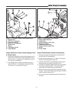
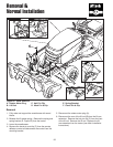
Install Hitch
Install the sub-frame hitch. Refer to sub-frame hitch
installation instructions. See also “Lift Variations...
on page 22 of this manual. Position the snowthrower in
front of the tractor.
Assemble Discharge Chute
1. Locate the hold downs (B, Figure 11), reinforcement
ring gear (D), and plastite screws (A).
2. Lubricate the base of the discharge chute and ring
gear with automotive lithium grease.
3. Remove the plastic cover (B, Figure 12) and loosen
the three taptite screws (A) securing the electric
spout rotator motor.
4. Install the discharge chute and reinforcement ring
gear (D), and secure to the chute ring (C, Figure 11)
using the three hold downs (B) and plastite screws
(A).
5. Adjust the motor so that it meshes with the discharge
chute ring gear and tighten the adjustment screws (A,
Figure 12).
Install Skid Shoes
1. Install the skid shoes using 3/8-16 x 3/4” carriage
bolts, washers, lockwashers, and nuts as shown in
Figure 13.
2. Adjust the skid shoes. See Adjustments section.