


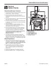
Intermediate Frame Snowthrowers
TP 300-4681-01-IW-SN 09/200718
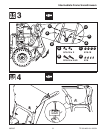
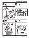
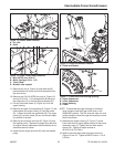
17. Slide spout rotator rod (B, Figure 14) into worm gear,
and secure with hair pin (A).
18. Install rotator cover (A, Figure 13) and secure with
5/16-18 flange lock nut (B). Tighten nut to 11 lb-ft (15
Nm).
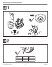
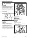
19. Install the auger drive belt (D, Figure 12) onto the
impeller pulley (H).
20. Slip the auger drive belt (D) under the idler pulley (K).
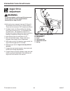
21. Adjust the auger drive belt. See “Belt Adjustment:
Auger Drive Belt” in the Adjustment section.
22. Adjust the belt guide. See “Belt Adjustment” in this
section.
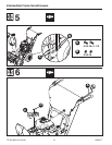
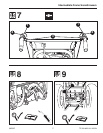
23. Install the belt cover (A, Figure 9). Tighten 1/4-20
screws (B) to 25-35 lb-in (2,8-3,9 Nm).
Note: Caution must be taken when tightening the screws
that secure the belt cover. Over tightening the screws
will deform the plastic.
24. Check the adjustment of the cables. See
“Adjustments - Auger Drive Adjustment and Traction
Drive Cable Adjustment” in the Adjustment section.
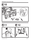
25. Install the bottom panel (B, Figure 11). Tighten 1/4-
20 screws to 25-35 lb-in (2,8-3,9 Nm).
26 Connect the spark plug wire.
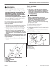
Traction Drive Belt
If the snow thrower will not move forward, check the trac-
tion drive belt for wear or damage. If the traction drive
belt is worn or damaged, replace the belt as follows.
1. Disconnect the spark plug wire.
2. Remove the auger drive belt. See “Belt Replacement”
in this section.
3. Remove the traction drive spring (E, Figure 12).
4. Remove the e-ring (J, Figure 12) from one end of the
swing plate axle rod (I).
5. Remove the swing plate axle rod (I) to allow the
swing plate (A, Figure 12) to pivot forward.
6. Remove the old traction drive belt (A) from the trac-
tion drive pulley (G) and from the traction drive pulley
(F). Replace the traction drive belt (A) with an origi-
nal factory replacement belt available from an
authorized Dealer.
7. Install the new traction drive belt (A) onto the traction
drive pulley (G) and onto traction drive pulley (F).
8. Make sure the traction drive idler pulley (L) is proper-
ly aligned with the traction drive belt (A).
9. Install the swing plate axle rod (I) and secure with the
e-ring (J) removed earlier.
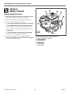
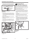
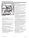
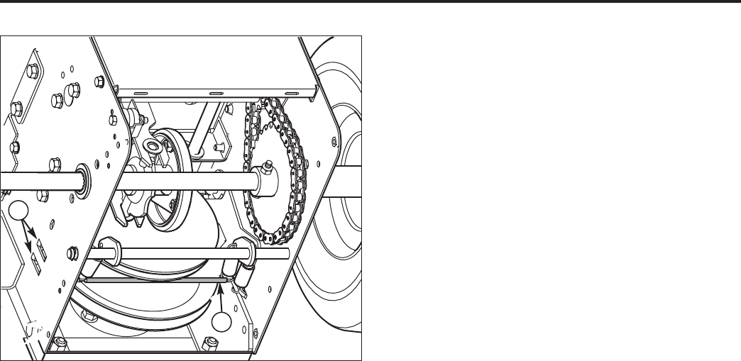
10. The bottom of the swing plate (A, Figure 18) must be
positioned between the alignment tabs (B). Make
sure the swing plate is properly secured.
NOTE: If the drive will not engage after the traction drive
belt has been replaced, then check to make sure that the
swing plate is positioned between the alignment tabs.
11. Attach the traction drive spring (E, Figure 12).
12. Install and adjust the auger drive belt. See Belt
Replacement in this section of the manual.
13. Adjust the belt guide. See Belt Adjustment in this
section of the manual.
14. Install the bottom panel (B, Figure 11). Tighten 1/4-
20 screws to 25-35 lb-in (2,8-3,9 Nm).
15. Install the belt cover (A, Figure 9). Tighten 1/4-20
screws (B) to 25-35 lb-in (2,8-3,9 Nm).
Note: Caution must be taken when tightening the screws
that secure the belt cover. Over tightening the screws
will deform the plastic.
16. Check the adjustment of the cables. See
Adjustments in this section of the manual.
17. Connect the spark plug wire.
Figure 18. Traction Belt Change
A. Swing Plate
B. Alignment Tabs
A
B