


Intermediate Frame Snowthrowers
09/2007 13 TP 300-4681-01-IW-SN
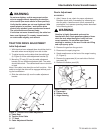
WARNING
Do not over-tighten, as this may cause traction
drive to engage without depressing the traction
drive control (arm must remain in down position).
Verify that the cables are not over-tightened: With
speed selector in position 1 and traction drive
control fully released, push snowthrower forward.
The unit should move forward freely.
If unit does not move forward freely, the cable has
been over-tightened. To remedy, loosen tension
on clutch cable slightly, and recheck.
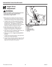
TRACTION DRIVE ADJUSTMENT
Initial Adjustment
1. With the drive lever released there should be slack in
the cable when moved slightly from side to side.
2. To adjust tension on the cable slide the cable boot
(A, Figure 4) off the cable adjustment bracket (D).
3. Move the “Z” hook (C) from the cable adjustment
bracket (D) to a different adjustment hole. The cable
should have slack. The cable should have no tension
or load.
Note: If the cable is too slack the unit will not drive. If the
cable is too tight the drive will be engaged without push-
ing the handle down.
4. Slide the cable boot (A) over the cable adjustment
bracket.
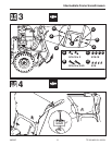
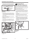
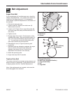
Figure 4. Traction Drive Cable Adjustment
A. Cable Boot
B. Traction Drive Cable
C. “Z” Hook
D. Cable Adjustment Bracket
C
A
B
D
B
C
Run-In Adjustment
ALL MODELS
1. After 5 hours of use, check for proper adjustment.
Readjust clutch cable if necessary by increasing ten-
sion on cable. A small amount of arm movement is
permissible if unit passes operating checks described
in the Warning above.
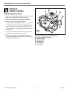
WARNING
Gasoline is highly flammable and must be
handled with care. Drain gasoline outdoors. Never
drain the tank when the engine is still hot from
recent operation. Do not allow open flame,
smoking or matches in the area. Avoid over-filling
and wipe up any spills.
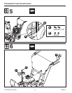
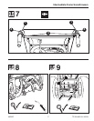
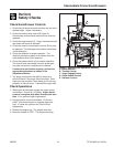
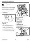
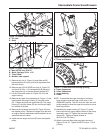
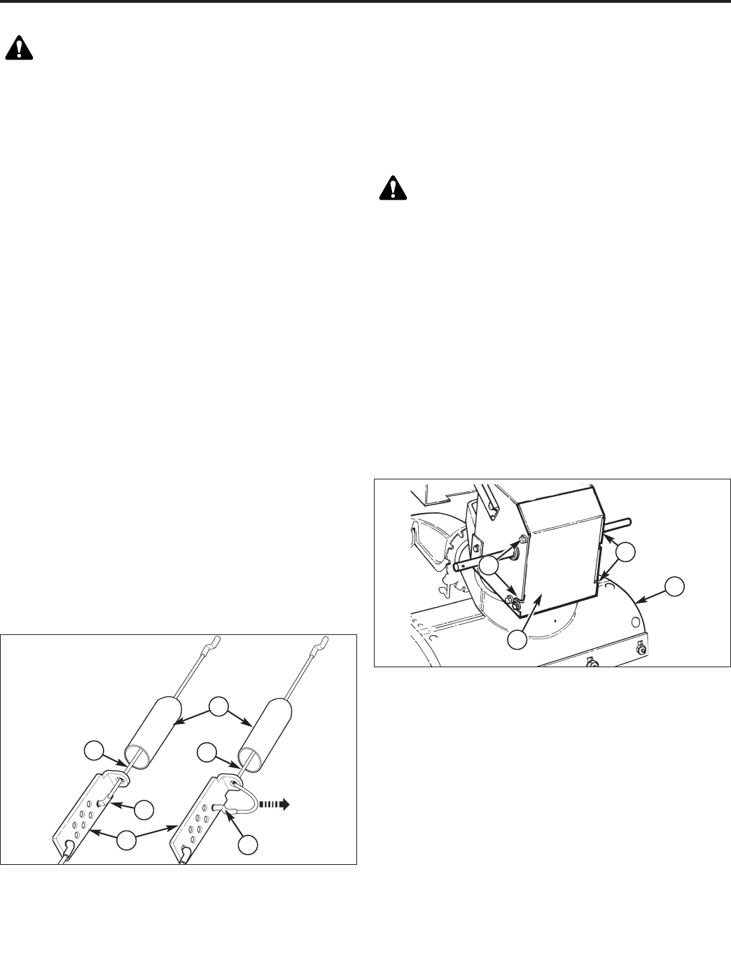
Figure 5. Bottom Cover
A. Capscrews
B. Bottom Panel
C. Auger Housing
C
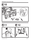
2. Remove the gas from the gas tank.
3. Disconnect the spark plug wire.
4. Stand snowthrower on the front of the auger housing
(C, Figure 5).
5. Remove the capscrews (A) on each side of the bot-
tom panel (B).
6. Remove the bottom panel (B).
B
A
A