


9
Operation
STARTING THE ENGINE
1. Turn the fuel valve (B, Figure 6) to the ON position.
2. Insert the Engine Key (F, Figure 6) into the Engine
Key slot and push fully in to the RUN position.
3. Move the Throttle Lever (E, Figure 6) fully up to the
FAST position.
4. Turn the Choke Knob (G, Figure 6) fully clockwise if
engine is cold. (Do not choke a warm engine.)
5. Push the Primer Button (D, Figure 6) two times if
engine is cold. (Do not prime a warm engine.)
6. Pull Starter Handle (C, Figure 6) rapidly, or push
Starter Button if equipped with the electric start. Do
not allow the Starter Handle to snap back—let the
starter rope rewind slowly—while keeping a firm grip
on the Starter Handle.
7. As the engine starts and begins to operate evenly,
turn the Choke Knob (G, Figure 6) slowly counter-
clockwise to the OFF position, and set the Throttle
Lever to SLOW. If the engine falters, turn the Choke
Knob clockwise until the engine runs smoothly, and
let it run briefly before returning the choke to the OFF
position.
NOTE: Allow the engine to warm up at SLOW throttle for
a few minutes before operating the snowthrower at full
speed. The engine will not develop full power until it
reaches operating temperature.
B
A
C
D
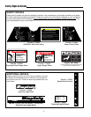
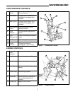
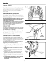
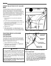
Figure 7. Operator's Control Position
FRONT
A. Speed Selector
B. Drive Control
C. Auger Control
D. Chute Direction Control
OPERATING THE SNOWTHROWER
1. Rotate the discharge chute to the desired direction.
2. Set the Speed Selector to the desired forward speed.
3. Fully press and hold the Auger Control (C, Figure 7)
on the right-hand grip to begin auger rotation. To dis-
engage the auger, completely release the lever.
4. Fully press and hold the traction Drive Control lever
(B, Figure 7) on the left-hand grip to engage the trac-
tion drive and begin moving the snowthrower. To dis-
engage the traction drive, completely release the
lever.
5. Select forward or reverse speeds as needed using
the Speed Selector (A, Figure 7). Release the Drive
Control lever whenever changing drive speeds.
NOTE: After 5 - 10 hours of use, it may be necessary
to adjust the tension on the traction drive rod. See
"Traction Drive Clutch Rod Adjustment" in the
Service Section for the adjustment procedure.
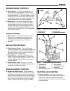
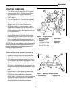
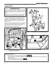
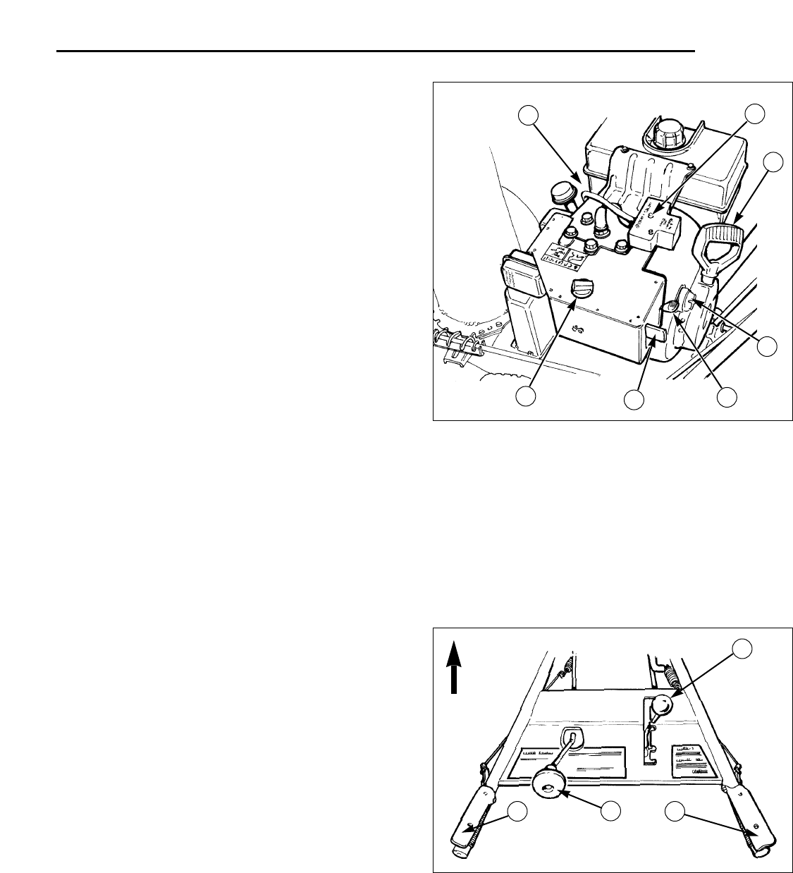
Figure 6. Engine Controls
A
E
F
C
D
G
B
*
A. Electric Start Button
(On some units only)
B. Fuel Valve
* 7 HP Engine
- Lower
Front Gas Tank Area
* 5 HP Engine
- Lower
Rear Gas Tank Area
C. Starter Handle
D. Primer Button
E. Throttle Lever
F. Engine Key
G. Choke Knob