


GROUND SPEED CONTROLS
A. Speed Selector - This lever (A, Figures 4 & 5) is
used to set the ground speed of the snowthrower.
The snowthrower has five forward speeds, 1–5, and
two reverse speeds, 1–2. No neutral position or gate
is required, since the traction drive design automati-
cally provides "neutral" (no forward or reverse move-
ment), whenever the Drive Control is released.
B. Drive Control - This control engages the traction
drive as the lever (B, Figures 4 & 5) is depressed,
and disengages the traction drive when the lever is
released. The traction drive provides power to the
wheels. NOTE: Changing ground speeds must only
be done while the Drive Control is in the disengaged
(fully released) position.
AUGER CONTROL
C. Auger Control - The Auger Control clutch lever (C
Figures 4 & 5), engages the auger drive (which
throws the snow) as the lever is depressed, and
disengages the auger drive when the lever is
released.
DEFLECTOR CONTROLS
D. Chute Direction Control - The Chute Direction
Control (D, Figures 4 & 5), allows the discharge chute
to be rotated to throw snow in the desired direction.
Snow may be thrown at any angle from straight left,
to straight forward, to straight right.
E. Chute Deflector - Controls the distance snow is
thrown. Tilting the Chute Deflector (E, Figure 5) UP
provides a higher stream and greater distance, while
tilting the deflector DOWN provides a lower stream
and less distance.
F. Chute Deflector Knob - This knob (F, Figure 5)
allows the discharge Chute Deflector (E, Figure 5) to
be locked in the desired tilt position.
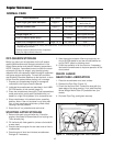
SCRAPER HEIGHT CONTROL
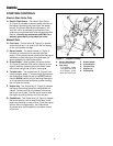
G. Scraper Bar Height Control - The Skid Shoes (G,
Figure 5) control the height the scraper bar (located
at the bottom of the auger housing). The scraper bar
allows smooth surfaces (such as concrete or asphalt
driveways) to be scraped clean of snow. On surfaces
such as gravel, the scraper bar should be adjusted
higher — so that it will not pick up gravel or debris.
7
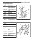
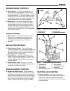
Controls
C
B
D
E
G
A
F
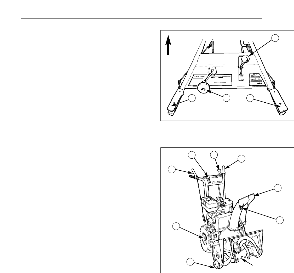
A. Speed Selector
B. Drive Control
C. Auger Control
D. Chute Direction Control
E. Chute Deflector
F. Chute Deflector Knob
G. Skid Shoes
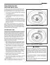
H. Traction Lock Pins
Figure 5. Snowthrower Operating Controls
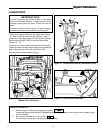
B
A
C
D
Figure 4. Operator's Control Position
FRONT
H
A. Speed Selector
B. Drive Control
C. Auger Control
D. Chute Direction Control
TRACTION LOCK CONTROL
H. Traction Lock Pins - The traction drive to each
wheel can be locked and unlocked with the Traction
Lock Pins (H, Figure 5) to permit the unit to “free-
wheel,” allowing easier manual handling and transport
of the snowthrower.
Scraper Bar