


31
Troubleshooting, Adjustment & Service
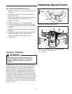
WARNING
Before checking mower, shut off PTO and engine.
Allow all moving parts to stop. Remove ignition
key, then disconnect the spark plug wires and
fasten them away from the spark plugs.
MOWER ADJUSTMENTS
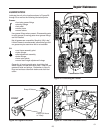
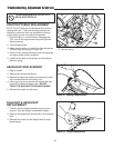
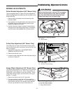
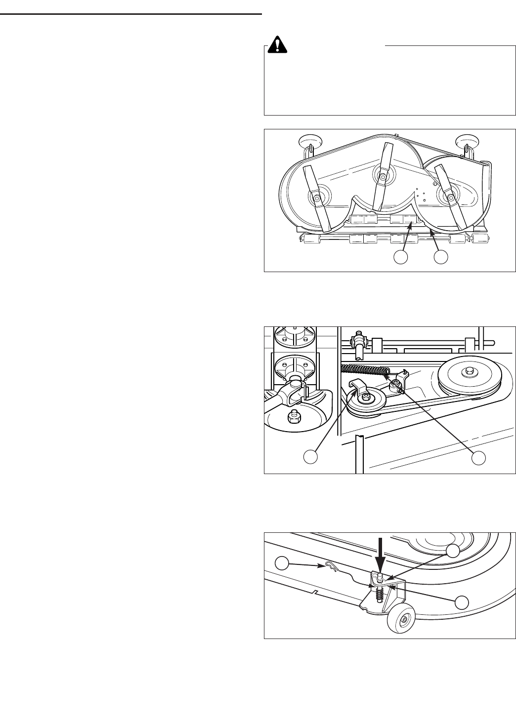
Roller Bracket Adjustment (60” Mower Only)
The anti-scalping rollers (A, Figure 44) can be adjusted for
different cutting heights by positioning roller brackets on the
mower baffle (B).
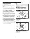
1. Remove bolts, lockwashers and nuts securing roller
bracket to baffle.
2. If you typically cut using the lower half of the mower cut-
ting height range, the roller brackets should be posi-
tioned in the upper set of holes.
3. Use the lower set of holes if mowing is usually done in
the upper half of the cutting height range, or if scalping
occurs at lower cutting heights due to uneven terrain.
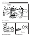
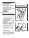
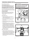
Figure 45. Pulley Stop Position
A. Pulley Stop
B. Idler Arm Tension Spring
Figure 44. Anti-Scalping Rollers
A. Rollers
B. Mower Baffle
A
B
B
A
Pulley Stop Adjustment (48” Mower Only)
The pulley stop (A, Figure 45) prevents the idler pulley
from contacting the idler arm tension spring (B) when the
deck is engaged.
1. Remove the mower deck. See MOWER DECK
REMOVAL & INSTALLATION.
2. Remove the left side cover.
3. Loosen the idler pulley bolt and orient the pulley stop (A)
as shown in Figure 45.
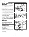
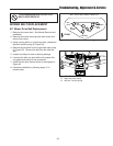
Gauge Wheel Adjustment (54” Mower Only)
The mower gauge wheels can be placed in two positions
depending on the height of cut. When using higher cut-
ting heights, set the wheels in the lower position. When
using lower cutting heights, set the wheels in the upper
position. To adjust:
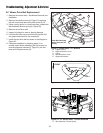
1. Remove the hair pin clip (A, B, Figure 46).
2. For upper position, install the pin (A) through the
spindle above the bracket (C). For the lower position,
push down on the top of the spindle, and install the
hair pin clip (B) below the top of the bracket (C).
Figure 46. Gauge Wheel Adjustment
A. Hair Pin (Upper Position)
B. Hair Pin (Lower Position)
C. Gauge Wheel Bracket
A
B
C