


29
WARNING
To avoid serious injury, perform adjustments only
with engine stopped, key removed and tractor on
level ground.
Troubleshooting, Adjustment & Service
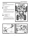
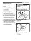
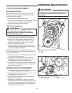
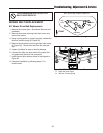
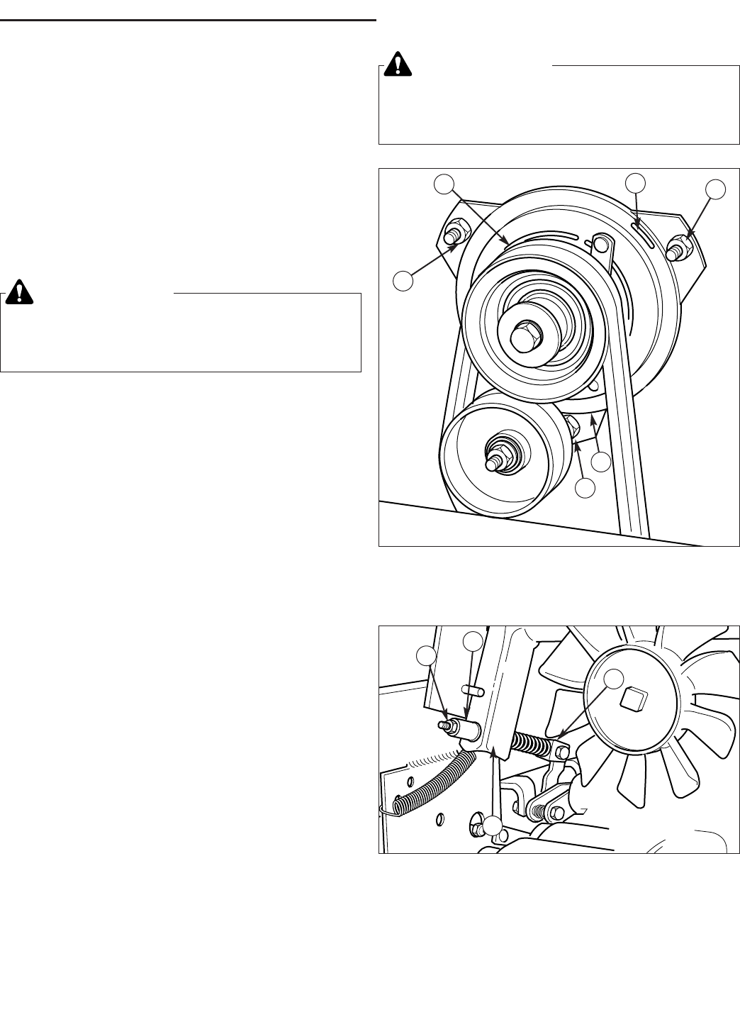
Figure 39. Front PTO Adjustment
A. Slots
B. Nuts
PTO CLUTCH ADJUSTMENT
Burnishing The Clutch
Before the front PTO clutch is used for the first time, it
should be burnished as follows. To burnish the clutch,
the mower must be installed.
1. Start the engine and set at full throttle.
2. Pull the front PTO switch out to the on position, leave
for 15 seconds, then push in to the off position.
3. Repeat ten times to burnish the clutch.
PTO Clutch Adjustment
1. Remove the tractor hood by disconnecting the head-
light coupler and then removing two hinge hooks.
2. Use a 0.015” feeler gauge to check front clutch at
three slots (A, Figure 39). There should be a slight
resistance as gauge is moved in and out of slot. If
tight or loose, proceed to step 3.
3. Loosen or tighten one of the nuts (B, Figure 39) to
achieve slight drag on feeler gauge. Check the other
two slots and adjust accordingly.
NOTE: Adjustment at one location will change adjust-
ment at the two other slots. Make sure all three locations
have proper adjustment.
4. With tractor in neutral, PTO disengaged and operator
in seat, start the tractor engine.
5. Engage the front PTO and wait several seconds.
Disengage the front PTO and check the amount of
time it takes for the mower drive belt to stop.
6. If mower drive belt does not stop within five seconds,
repeat steps 1-3. If the belt still does not stop within 5
seconds, see your dealer.
BRAKE LINKAGE ADJUSTMENT
1. Turn off the engine and remove the key from the igni-
tion. DO NOT engage the parking brake.
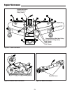
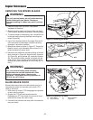
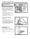
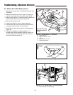
2. Remove the back bumper to gain access to the brake
rod adjustment nut (A, Figure 40).
3. Angle the brake assembly arm so that is standing
straight up. Hold in place.
4. With the brake assembly arm straight up and the
brake pedal at rest, turn the brake rod adjustment nut
(A, Figure 40) until the spacer (C) contacts the brake
pivot arm (D). Do not over-tighten. Over-tightening
will cause the brake to drag.
Figure 40. Brake Linkage Adjustment
A. Brake Rod Adj. Nut C. Spacer
B. Brake Assy. Arm D. Brake Pivot Arm
B
A
C
D
A
A
A
B
B
B
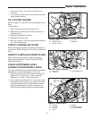
WARNING
The muffler and surrounding areas can be
extremely hot. Allow the engine to cool before
performing this procedure.