


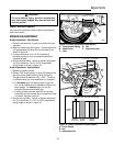
Front-To-Back Levelling
1. Make sure mower is level side-to-side and that rear
rollers are on the ground.
2. Position blade(s) front-to-back. Measure the distance
from the ground to front tip of blade(s), and from
ground to rear tip of blade(s).
On 30” mower, the front tip should be level to 1/8”
(3 mm) higher than rear tip.
On 34” mower, the front tips should be 1/4” (6 mm)
higher than the rear tips.
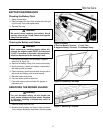
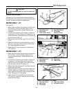
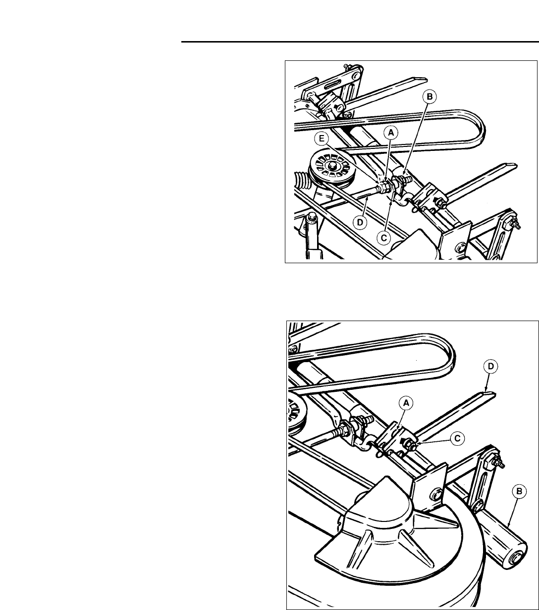
3. See figure 33. Loosen jam nut (E). To lower rear of
mower deck, loosen nut (B) which will lengthen level-
ing rod (D). To raise rear of deck, shorten leveling rod
(D). When proper measurement is obtained, tighten
nut (A) against bracket, then tighten jam nut (E)
against nut (A).
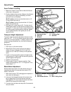
Transport Height Adjustment
Transport height should be adjusted so that rear mower
rollers are 1/8” - 1/4” (3-6 m) above ground when mower
lift lever is in transport position. To adjust, perform both
mower leveling procedures first, then do the following
procedure.
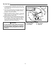
See figure 34.
1. Park rider on a flat level surface.
2. Adjust Dial-A-Cut
TM
control so that front edge of
mower lift lever is alligned with 2-3/4” mark (34”
mower) or at 3” mark (30” mower) on the quadrant
scale.
3. Loosen nut (C) and position spacer (A) against rear
trailing arms (D). Position both the left and right side
spacers against trailing arms.
4. Tighten nut (C) securely.
5. Place mower lift lever in transport position. Rear
mower rollers should be 1/8” - 1/4” off ground. If not,
repeat steps 2 - 4.
Blade Brake Adjustment
Mower blades and mower drive belt should come to a
complete stop within five seconds after electric PTO
switch is turned off.
1. With riderin neutral, PTO disengaged and operator in
seat, start the riderengine.
2. Look over the left-hand footrest at the mower drive
belt. Engage the PTO and wait several seconds.
Disengage the PTO and check the amount of time it
takes for the mower drive belt to stop.
3. If mower drive belt does not stop within five seconds,
see your dealer.
Figure 33. Front-To-Back Levelling
A. Adjustment Nut D. Levelling Rod
B. Rear Nut E. Jam Nut
C. Bracket
28
Adjustments
*2397
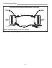
Figure 34. Transport Height Adjustment
A. Spacers C. Nut
B. Rear Mower Rollers D. Rear Trailing Arms
*2397