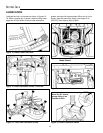
1. If you are ready to mow, lower the mower from the
transport position using lever (A, figure 11) and set
the mowing height using the Dial-A-Cut
TM
Control (E,
figure 11).
2. Set the engine speed control lever (M, figure 2) for
full speed.
3. Use the PTO switch (G, figure 2) to engage the PTO.
4. Release the parking brake by depressing the
clutch/brake pedal (D, figure 11) and pushing knob
(B) down.
5. On hydro models, move the ground speed control
lever (C, figure 11) to the desired direction and speed
of travel to set the rider in motion.
On gear models, depress clutch/brake pedal, use
the ground speed control lever to select the proper
gear for conditions, then slowly release clutch/brake
pedal to set the rider in motion.
6. Adjust engine speed control lever (M, figure 2) to the
desired speed. Between 3/4 and full speed is recom-
mended for mowing.
3. Use the PTO switch (G, figure 2) to disengage the
PTO.
4. Set the engine speed control lever (M, figure 2) to 1/2
throttle setting and allow the engine to idle for 20 sec-
onds. Stopping a hot engine too fast may cause
engine damage.
5. Turn key (C, figure 2) to OFF and remove it.
NEUTRAL SAFETY CHECKS
NEUTRAL GATE CHECK: The unit should not move when
the ground speed control lever is in the neutral gate.
RETURN-TO-NEUTRAL CHECK: On Hydrostatic
equipped models, the ground speed control lever should
return to the neutral gate when the cluthc/brake pedal is
fully depressed.
If the unit fails either of these checks, the unit should
be properly readjusted by an authorized servicing
dealer before use.
Do not tow the rider.
Damage will result to the
transmission/axle.
12
WARNING
Before leaving the operator’s position for any
reason, engage the parking brake, disengage the
PTO, stop the engine and remove the key.
WARNING
To reduce fire hazard, keep the engine, rider and
mower free of grass, leaves and excess grease.
Do not stop or park rider over dry leaves, grass
or combustible materials.
Operation
WARNING
Make sure desired direction of travel is clear of
objects, people and animals.
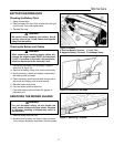
PUSHING THE RIDER BY HAND
Hydro Models
1. Engine should be off and ignition key removed.
2. Place the mower in the transport position (up) using
the mower lift lever (A, figure 11).
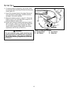
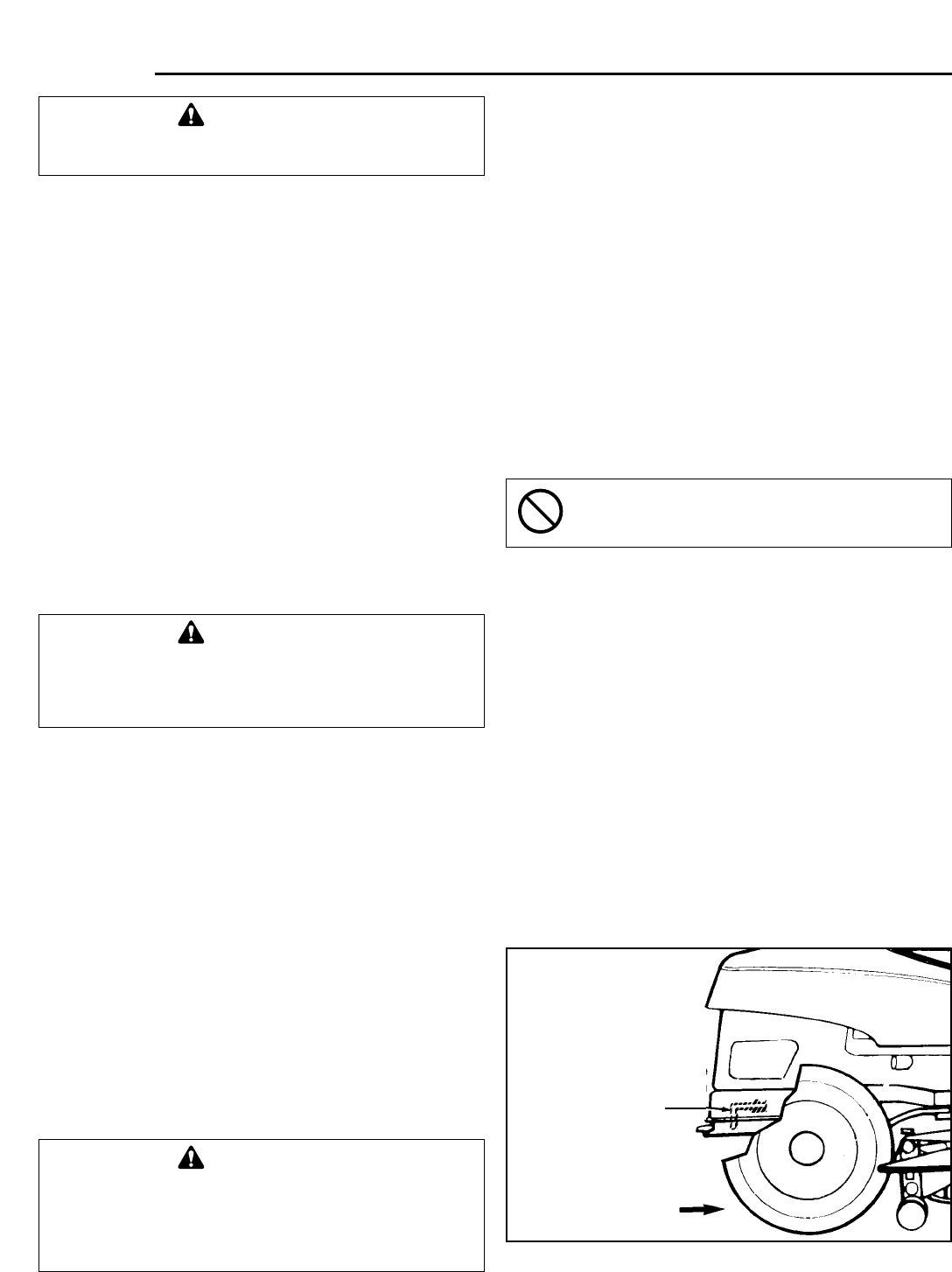
3. See figure 12. To push the rider by hand, the release
lever must be placed in the PUSH position.
4. To drive the rider, release lever must be moved to the
DRIVE position.
Gear Model
1. Engine should be off and ignition key removed.
2. Place the mower in the transport position (up) using
the mower lift lever (A, figure 11).
3. Depress the clutch/brake pedal and place the ground
speed control lever (C, figure 11) in the neutral gate.
4. Unlock the parking brake.
Figure 12. Transaxle Release Lever - Hydro Models
*2511
Move forward for drive
position, pull rearward
for push position.
Forward
STOPPING THE RIDER
1. On hydro models, move the ground speed control
lever (C, figure 11) into the NEUTRAL position to
make a gradual stop. To make a more rapid stop,
depress the clutch/brake pedal (D, figure 11).
NOTE: On hydro models, the ground speed control
lever will return to neutral from forward automatically
when the clutch/brake pedal is depressed.
On gear models, press the clutch/brake pedal (D,
figure 11) down only far enough to disengage the
clutch to make a gradual stop. For a more rapid stop,
press pedal down farther to apply the brake. Move
the ground speed control lever to NEUTRAL before
releasing the pedal.
2. Engage the parking brake by fully depressing
clutch/brake pedal and pulling up on parking brake
knob (B, figure 11).


