


25
SEAT ADJUSTMENT
Use the lever to adjust the seat forward or rearward for
best rider comfort.
BRAKE ADJUSTMENT
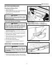
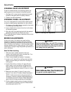
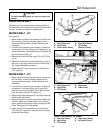
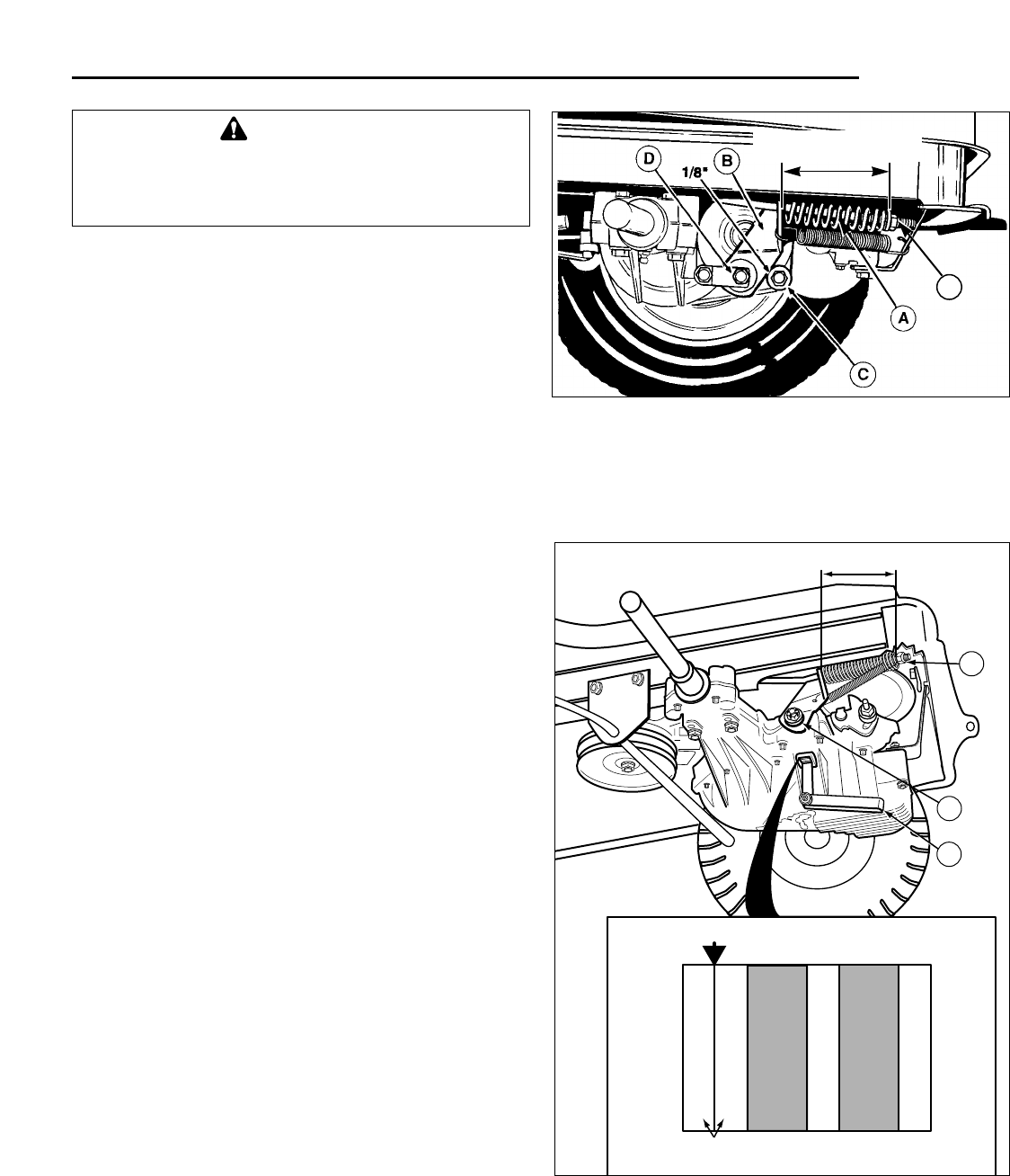
Brake Adjustment - Gear Models
1. Place the transmission in gear and release the park-
ing brake.
2. Move the brake lever (B) forward. There should be a
1/8" gap between the lever (B) and the stop (C) as
shown in figure 24.
3. To adjust clearance, turn nut (D) clockwise to
decrease the gap or turn nut counterclockwise to
increase the gap.
4. Set the parking brake. Loosen or tighten adjustment
nut (E) to achieve a 2 9/16"–2 5/8" compressed
spring length as shown in figure 24.
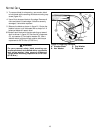
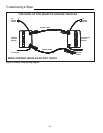
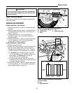
Brake Adjustment - Hydro Models
1. Release the parking brake.
2. Place a .025" feeler gauge (A, figure 25) between the
two outer brake stators (refer to inset illustration).
The gap should be between .025"–.030". To adjust:
a. Remove cotter pin from castellated nut if present.
b. To decrease gap, hold feeler gauge in gap and
turn nut (B) clockwise until resistance is felt on the
feeler gauge. To increase gap, turn nut (B)
counter-clockwise and recheck gap.
c. If cotter pin was removed, back off nut (counter-
clockwise) until the nearest slot is aligned with hole
in threads. Replace cotter pin.
3. Set the parking brake. Loosen or tighten adjustment
nut (C) to achieve a 2 11/16"–2 13/32" compressed
spring length as shown in figure 25.
Adjustments
WARNING
To avoid serious injury, perform adjustments
only with engine stopped, key removed and rider
on level ground.
CHECK GAP with .025" FEELER GAUGE
OUTER
BRAKE
OUTSIDE
(Axle)
INSIDE
(Trans.)
INNER
BRAKE
OUTER
STATORS
B
C
2 11/16" – 2 13/32"
A
Figure 25. Brake Adjustment (Hydro Model)
A. Feeler Gauge
B. Nut
C. Adjustment Nut
Figure 24. Brake Adjustment (Gear Model)
A. Compressed Spring D. Nut
B. Brake Lever E. Adjustment Nut
C. Stop
*2393
2 9/16" – 2 5/8"
E